
Dual laser frequency sweep interferometry system and method

a laser frequency sweep and interferometer technology, applied in the direction of measurement devices, instruments, structural/machine measurement, etc., can solve the problems of large disturbance of signals, large doppler shift, and large increase of distance measurement uncertainty, so as to improve signal integrity, improve snr, and increase operating range

Active Publication Date: 2019-01-01
NPL MANAGEMENT
View PDF16 Cites 4 Cited by
  • Summary
  • Abstract
  • Description
  • Claims
  • Application Information

AI Technical Summary

Benefits of technology

The present invention is a scalable and flexible optical arrangement that compensates for drift using fibre end reflection and increases the optical gain by separating out local oscillators for two frequencies. It operates using differing frequency swept laser sources as the FWM will work for any sweeping speed of the original signals. This results in a more powerful laser source without affecting the maximum power output from the fibre end.

Problems solved by technology

Different alternatives of this design have been suggested, ranging from simple systems that rely on frequency only to more complex systems that add phase measurement (which improves precision but the system is less flexible due to additional references required and problems arise if the signal is lost at any point).
In non-ideal situations, a problem appears when the target is moving, either intentionally or due to vibration, or if the optical path is changing due to e.g. air motion, and thus τ has a dependence of t. As f0 is large in comparison to the other terms in the argument of the cosine, even small variations of T during a measurement can cause a large disturbance to the signal.
This Doppler shift greatly increases the distance measurement uncertainty, both through increasing the variance of measurements when the target movement is random between measurements (e.g. when caused by vibration), and by the presence of systematic errors present when the target motion is at a constant rate.
The tuneable lasers required in dual-sweep FSI systems are often the most expensive component in this type of system (particularly if high precision is required which requires large mode-hop-free tuning range), and synchronising their frequency sweeps with sufficient accuracy can be difficult.
Generally, the larger the tuning range of the laser the greater the cost.
However, despite improvements, the approach remains very expensive and complex to implement and maintain.
This limits the amount of signal gain that can be obtained by increasing the measurement beam amplitude.
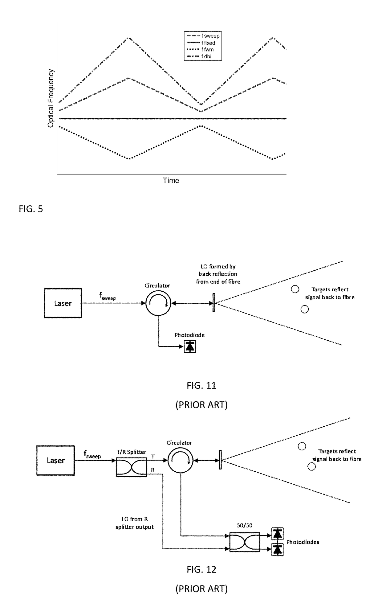
However, taking the LO signal from the fibre end in this way limits the amount of signal gain that can be achieved.
The draw-back of this approach is that the LO and measurement beams no longer take a common path through the optical fibres, so any disturbance to the fibres due to, for example, temperature change or other stresses will result in drift in the distance measurements.

Method used


Image

  • Dual laser frequency sweep interferometry system and method
  • Dual laser frequency sweep interferometry system and method
  • Dual laser frequency sweep interferometry system and method

Examples


Embodiment Construction

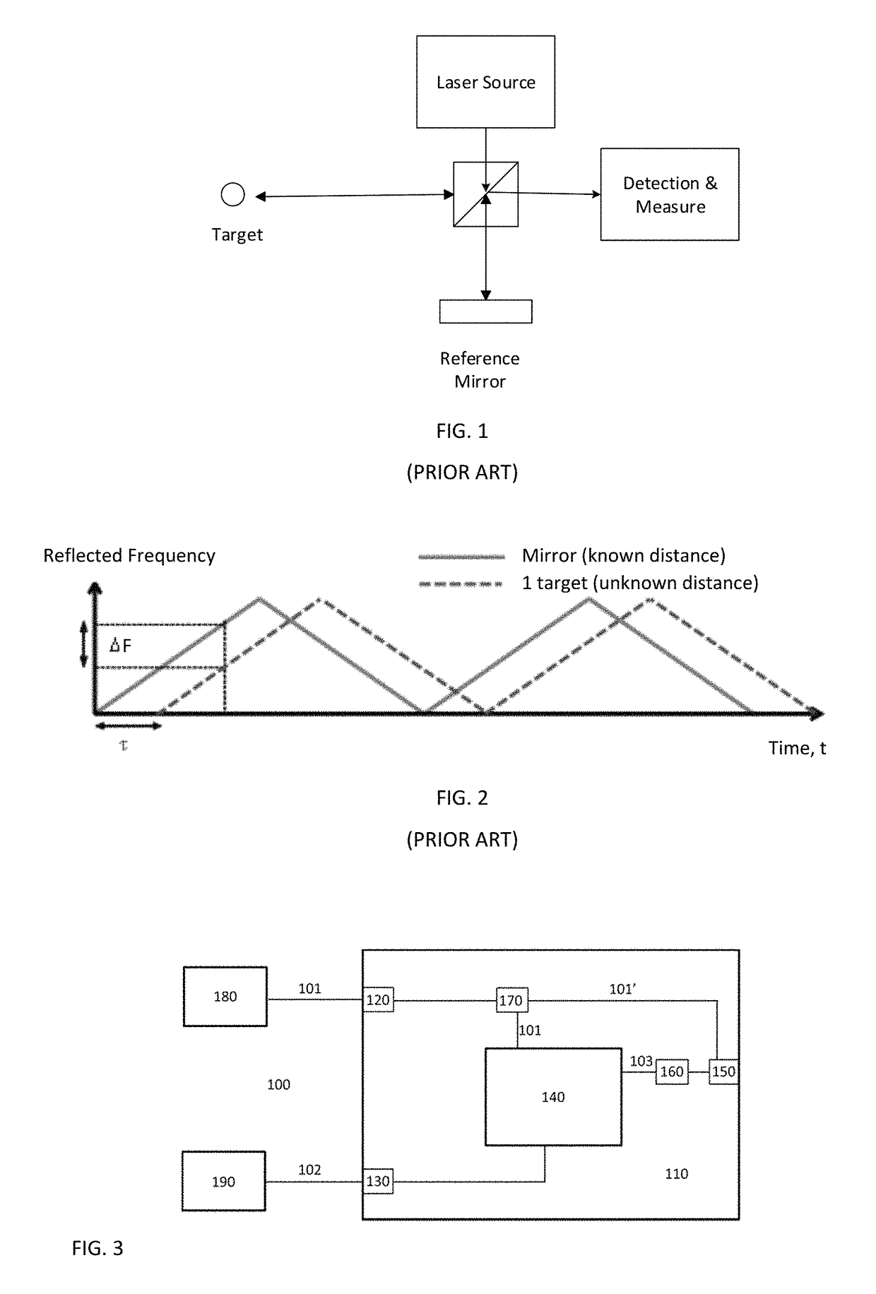
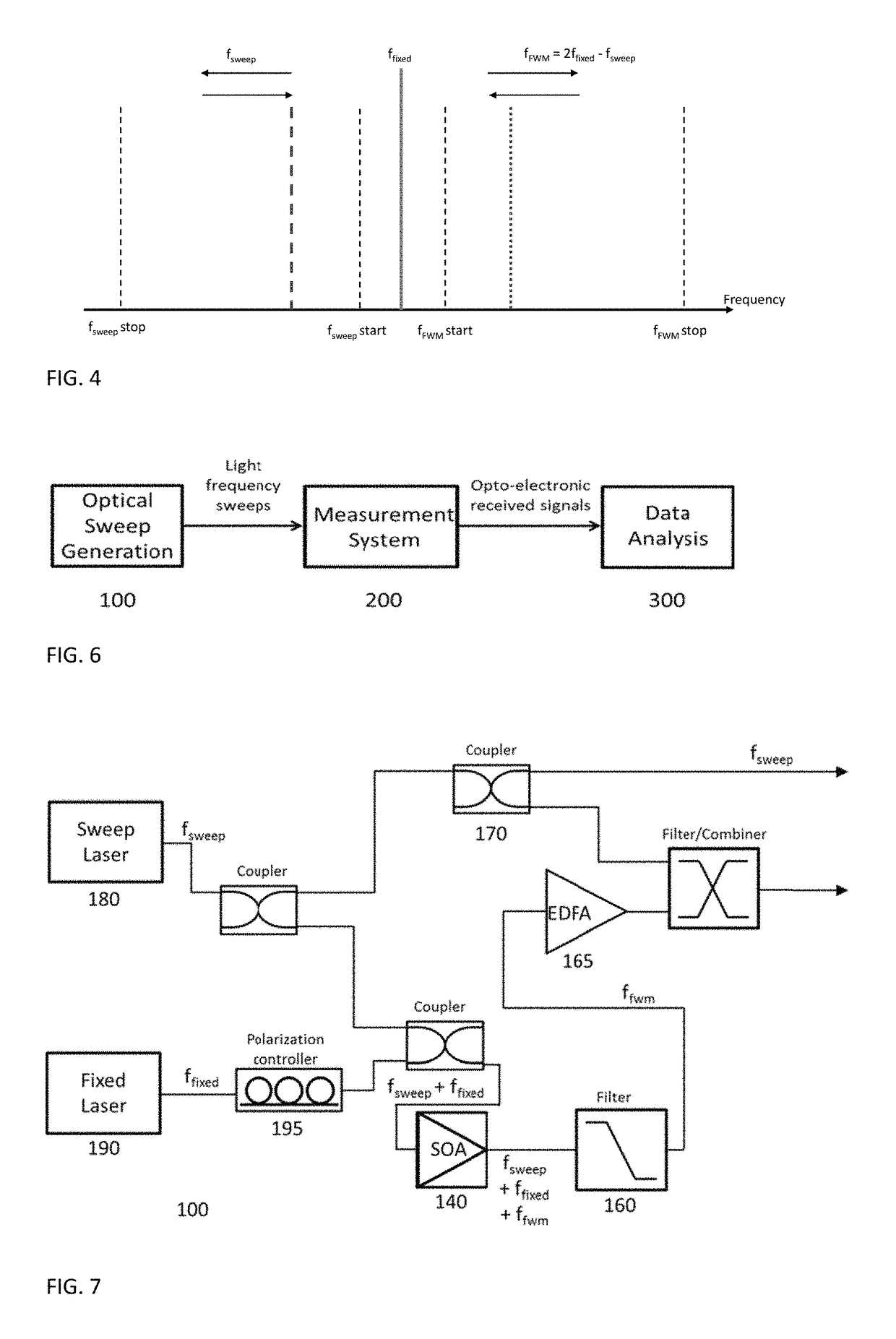
[0135]FIG. 3 is a schematic diagram of sweep generation system 100 including an optical arrangement according to and embodiment of the present invention.

[0136]The sweep generation system 100 includes an optical arrangement 110 having a first input 120, a second input 130, a non-linear optical artefact 140 and an output 150.

[0137]The first input 120 is arranged to receive a first beam 101 from a frequency swept laser 180. The second input 130 is arranged to receive a second beam 102 from a fixed frequency pump laser source 190. The optical frequency separation of the first 101 and second 102 beams are satisfy the coherence length condition of non-linear optical artefact 140.

[0138]The non-linear optical artefact 140 is arranged to receive, and to intermodulate by four wave mixing, the first 101 and second 102 beams to generate a third beam 103, the third beam 103 being an inverted copy of the first beam 101 mirrored relative to the fixed frequency of the pump laser source 190.

[0139]Th...


PUM

PropertyMeasurementUnit
reflectanceaaaaaaaaaa
wavelengthsaaaaaaaaaa
refractive indexaaaaaaaaaa

Abstract

An optical arrangement, method and measurement system are disclosed. The arrangement includes a first input to receive a first beam from a frequency swept laser, a second input to receive a second beam from a fixed frequency pump laser source. A non-linear optical artifact receives and intermodulates the first and second beams to generate a third beam, the third being an inverted copy of the first beam mirrored relative to the fixed frequency of the pump laser source. A selective combining element outputs the first and third beams. The non-linear artifact or one or both of the lasers is selected or configured such that the optical frequency separation of the first and second beams satisfies the coherence length condition of the non-linear artifact.

Description

FIELD OF THE INVENTION[0001]The present invention relates to a system and method for use in dual laser frequency sweep interferometry (dual sweep FSI).BACKGROUND TO THE INVENTION[0002]Interferometry measurement is a technique to measure the distance to a target or targets using wavelengths such as light. It can be used in many different fields and applications including: long distance measurement, 3-dimensional positioning where the ability to measure simultaneously to multiple targets from a single interferometer is particularly advantageous (using mainly frequency only) and small displacements (using also phase) for engineering and aerospace applications; surface inspection and imaging for quality control devices; short range detailed imaging for biological applications like the optical coherence tomography (OCT) techniques.[0003]Frequency Scanning Interferometry (FSI, also known as Frequency Sweeping Interferometry) is one type of interferometry that is used to measure the distan...

Claims


Application Information

Patent Timeline
Patent Type & Authority Patents(United States)
IPC IPC(8): G01B9/02G01B11/02G01S17/32G01S7/491G02F1/35G01S7/4911G01S7/4915G01S17/34
CPCG01B9/02007G01B9/02004G01B9/02027G01B9/02084G02F1/3536G01S7/4911G01S7/4915G01S17/325G01B11/026G01S17/34G01B9/02G01M11/00
Inventor MARTINEZ, JUAN JOSECOPNER, NIGEL JOSEPHWARDEN, MATTHEW STUARDHUGHES, EDWARD BENJAMINCAMPBELL, MICHAEL ALOYSIUS
Owner NPL MANAGEMENT
Learn More