Lubrication and cooling system

a technology of lubrication and cooling system, applied in the direction of machines/engines, liquid fuel engines, lighting and heating apparatus, etc., can solve the problems of reducing the lubricity of the oil, raising the temperature of the oil, and limiting the system when operating at higher evaporation, so as to reduce the pressure of the refrigerant gas

Active Publication Date: 2019-02-05
JOHNSON CONTROLS TYCO IP HLDG LLP
View PDF21 Cites 2 Cited by
  • Summary
  • Abstract
  • Description
  • Claims
  • Application Information

AI Technical Summary

Benefits of technology

[0011]The present invention solves the problem of refrigerant absorption or refrigerant solubility in oil in compressors operating at elevated temperatures. The refrigerant system includes a compressor, a condenser, and an evaporator. The compressor compresses low pressure refrigerant gas to a higher pressure refrigerant gas. The high pressure refrigerant gas is condensed into a high pressure liquid. An expansion valve between the condenser and the evaporator reduces the pressure of the high pressure liquid and may produce a low pressure mixture of gas and liquid which is then sent to the evaporator. The evaporator changes the state of the liquid to a gas while providing cooling, and the low pressure gas is resent back to the compressor. The system also includes a sump that collects oil used to lubricate the compressor. The sump is usually located below the compressor or at a low point of the compressor to gather oil from compressor lubrication by gravity. While this system as described above is well known, the present invention further includes a pressure reducing device positioned between the oil sump and a low pressure side of the refrigerant system. This device lowers the pressure of the refrigerant gas in the oil sump to a pressure substantially lower than the gas pressure at the compressor suction.
[0012]Lowering the pressure of refrigerant in the oil sump has the effect of reducing the dilution of refrigerant in the oil, which has several beneficial effects. The reduced miscibility of refrigerant in the oil mitigates the reduction of oil viscosity due to temperature / pressure, resulting in higher oil viscosity. As the reduction of the dilution in the prior art is achieved by increasing the temperature of the oil, thereby resulting in expulsion of refrigerant from the oil, but undesirably raising the temperature of the oil and reducing its lubricity. Achieving reduction of dilution by lowering the pressure of refrigerant in the sump also has the effect of reducing the need to increase this oil temperature. This lower oil temperature also results in a better control of the viscosity of the oil and better lubricity. Better lubricity also reduces the risk of deterioration on certain components of the compressor, like shaft seals and bearings, while also reducing the likelihood of breakdown of the oil and extended oil life.
[0014]The use of a device to lower the refrigerant pressure in the motor housing as refrigerant traverses the motor has the beneficial effect of keeping the refrigerant fluid used to cool the motor at a low temperature, even if the evaporation temperature and pressure in the evaporator increase due to the higher heat pump temperatures. Reduced pressure in the motor also may provide a reduction of the gas friction power generated by the speed of the rotating parts, which in turn results in lower friction losses, further helping to reduce motor heating and contribute to motor cooling. In addition to cooling the motor, the refrigerant can be beneficially used to cool bearings that also are located in the motor housing. These bearings can be electromagnetic bearings that require no lubrication but which generate heat, or mechanical bearings that usually require lubrication, but also may be oil-free but generate mechanical heat.

Problems solved by technology

As the reduction of the dilution in the prior art is achieved by increasing the temperature of the oil, thereby resulting in expulsion of refrigerant from the oil, but undesirably raising the temperature of the oil and reducing its lubricity.
This is satisfactory for systems operating at normal air conditioning temperatures; but there are limits to the system when operating at higher evaporation temperatures, like in high temperature heat pumps.

Method used


Image

  • Lubrication and cooling system
  • Lubrication and cooling system
  • Lubrication and cooling system

Examples


Embodiment Construction

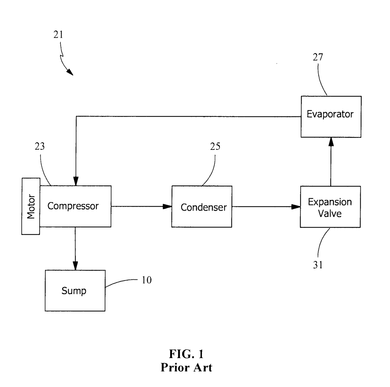
[0037]FIG. 1 is a schematic of a typical refrigeration system depicting a motor / compressor 23 in fluid communication with a condenser 25 which is in fluid communication with an evaporator 27. Refrigerant gas is compressed to a higher pressure in compressor 23. The high pressure refrigerant gas, after flowing to condenser 25 is condensed to a high pressure liquid via heat exchange, not shown. The high pressure refrigerant liquid is then sent to evaporator 27. An expansion valve 31 intermediate condenser 25 and evaporator 27 expands the high pressure refrigerant liquid to a mist, the mist being a mixture of gas and liquid at a lower temperature. In evaporator 27, the liquid refrigerant is evaporated, absorbing heat from a heat exchange fluid, as liquid refrigerant mist changes phase from liquid to gas. The cooled heat exchange fluid may be sent directly to a building environment or indirectly to an intermediate medium, such as a chiller for storage of chilled water until required. Ref...


PUM


Abstract

A system for reducing the refrigerant pressure in an oil sump (10) or in a cavity (352) of a housing. The invention is particularly useful for reducing pressure in a compressor (23) for heat pump applications that has been validated for water chiller operations or in turbine and generator systems in ORC systems generating electricity using refrigerant, the ORC systems essentially being a heat pump application operating in reverse. An auxiliary compressor (509), an auxiliary condenser (709) or an ejector pump (609) may be used to reduce pressure in the oil sump (10), to separate refrigerant from oil. The auxiliary compressor (509), the auxiliary condenser (709) or the ejector pump (609) may also be used to reduce the pressure of refrigerant in the housing of a compressor in heat pump applications at temperatures and pressures at which the compressor was validated for water chiller applications and of the turbine and generator in ORC applications.

Description

FIELD OF THE INVENTION[0001]This invention is generally directed to reducing the amount of miscible refrigerant in lubricant in lubrication systems used in refrigeration systems heat pumps and organic Rankine cycle (ORC) systems, and specifically to reducing the amount of refrigerant in lubricating oil, or alternatively, to reduce the refrigerant pressure in the housing of a semi-hermetic or hermetic motor or generator used in a refrigerant circuit so as to improve the cooling of the motor or generator.BACKGROUND OF THE INVENTION[0002]Centrifugal compressors are routinely used for medium to large capacity water chillers used for air conditioning or process applications, with a chilled water temperature leaving the chiller to the space to be cooled typically of the order of about 7° C. (45° F.). In order to generate energy savings and benefit from renewable energies, there is a growing demand for heat pumps. In some applications, the “cold source” of such heat pumps can be at a relat...

Claims


Application Information

Patent Timeline
Patent Type & Authority Patents(United States)
IPC IPC(8): F25B43/02F04D25/06F04D29/063F04D29/58F25B31/00F01K25/08F04D17/12F25B1/053
CPCF25B43/02F01K25/08F04D17/12F04D25/06F04D29/5806F25B31/004F25B31/008F04D29/063F25B2500/16F25B1/053F25B11/00F25B39/04F25B2600/05F25B41/20
Inventor DE LARMINAT, PAUL MARIEARNOU, DAMIEN JEAN DANIEL
Owner JOHNSON CONTROLS TYCO IP HLDG LLP
Why Eureka
Try Eureka