
Methods for making carbon fibers for high temperature applications

a technology of carbon fiber and high temperature, applied in the direction of fiber treatment, fiber treatment, transportation and packaging, etc., can solve the problems of significant differences in the suitability of the resulting fiber for thermal protection systems, inability to produce toxic waste products, and inability to meet the requirements of high-temperature applications

Active Publication Date: 2019-04-16
UNIVERSITY OF ALABAMA
View PDF3 Cites 2 Cited by
  • Summary
  • Abstract
  • Description
  • Claims
  • Application Information

AI Technical Summary

Benefits of technology

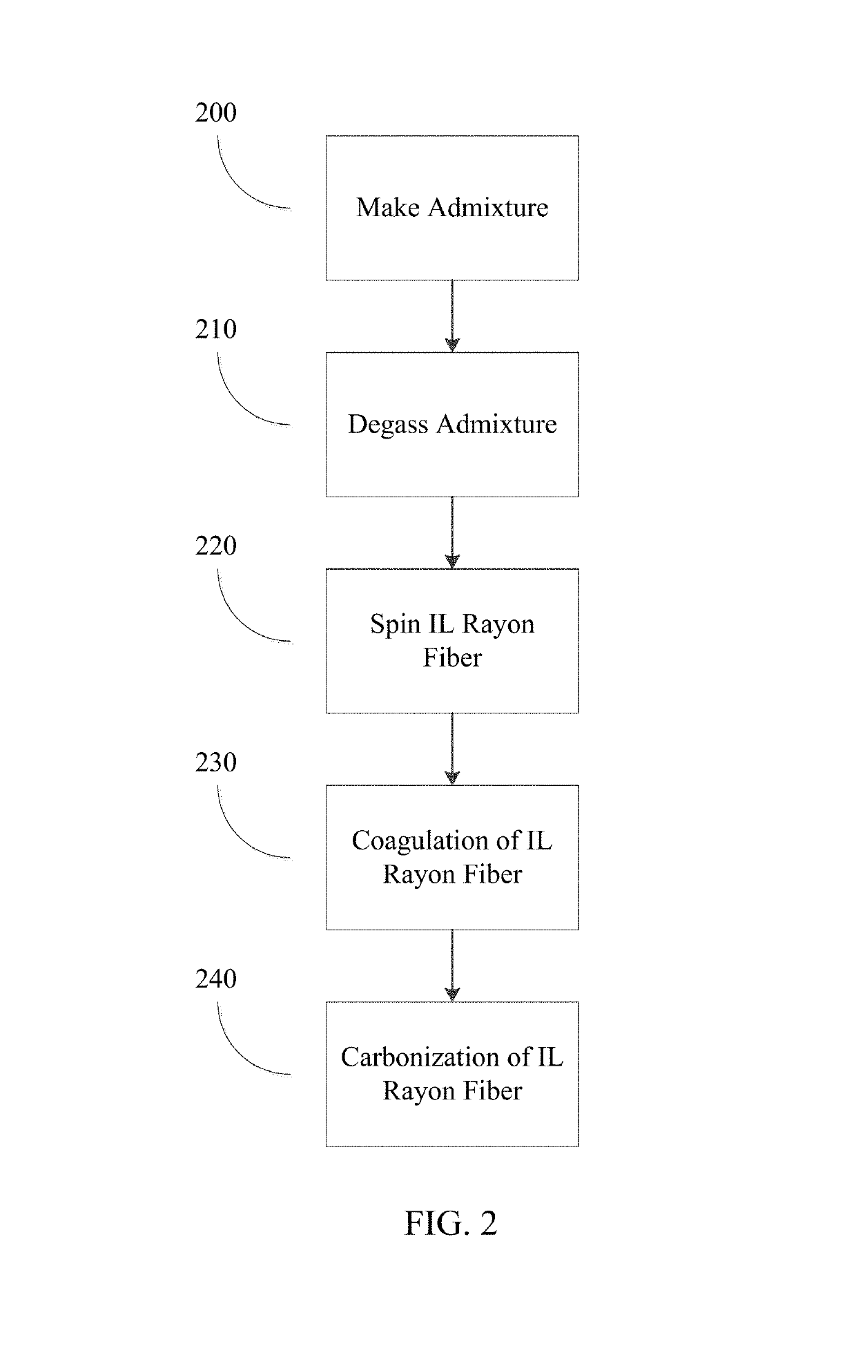
The present patent relates to a method of preparing carbon fiber by mixing cellulose with an ionic fluid, degassing the mixture, spinning it into ionic liquid (IL) rayon fibers, drying and washing the fibers, and then carbonizing them at high temperature. The method includes a carbonizing step that involves increasing the temperature of the IL rayon fibers from room temperature to a high temperature, and then reducing it back to room temperature. The carbonization process can also involve maintaining the temperature at a high level for a certain period of time. This method is efficient in producing carbon fiber with improved properties.

Problems solved by technology

Differences in the method of producing such fibers, however, such as the rate of heating and washing of the fibers, can lead to significant differences in the suitability of the resulting fibers for thermal protection systems.
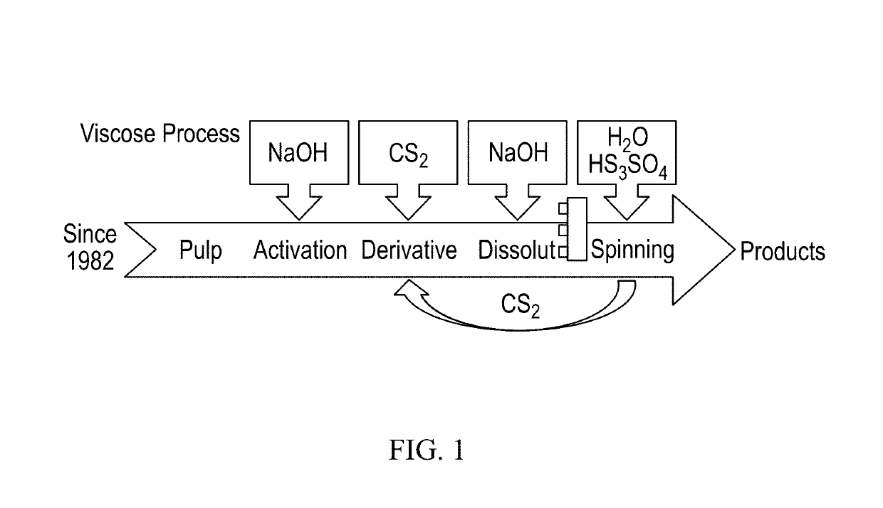
This method utilizes wood (cellulose and lignin) as a source of cellulose and results in the production of toxic waste products, such as carbon disulfide, lignin and the xanthates.
The Environmental Protection Agency implemented regulations which make the production of viscose rayon cost prohibitive.
As a result, such viscose rayon is no longer commercially produced in the United States.
NASA and the Department of Defense stockpiled millions of pounds of such viscose rayon for rocket nozzle construction in the early 1990s in anticipation of these environmental regulations, but these stockpiles are now nearly depleted.

Method used


Image

  • Methods for making carbon fibers for high temperature applications
  • Methods for making carbon fibers for high temperature applications
  • Methods for making carbon fibers for high temperature applications

Examples


Embodiment Construction

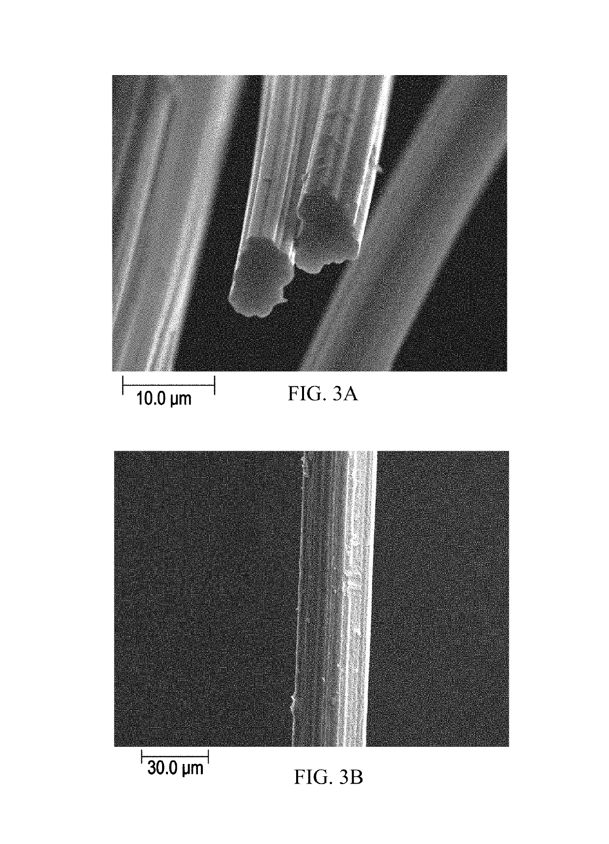
[0014]The present disclosure relates to methods and systems for the continuous production of cellulosic filament yarns with a compact, homogeneous structural morphology, and the low thermal conductivity carbon fibers produced by these methods. The disclosed methods utilize safe and recyclable ionic liquids (IL) to produce carbon fiber precursors from cellulose. In one embodiment, the fibers are produced by the carbonization of cellulose carbon fiber precursors. The fibers are manufactured from cellulose solutions in ionic fluids as part of a wet spinning process. The processing of the cellulose at near room temperature preserves the necessary degree of polymerization. The precursor fiber filaments have an increased tear resistance with simultaneously sufficient elongation, a round or crenulated cross-section, and homogeneous fiber morphology. The filament yarns exhibit performance characteristics similar to those produced from traditional viscose rayon. The resulting carbon fibers a...


PUM

PropertyMeasurementUnit
temperatureaaaaaaaaaa

Abstract

The present invention relates to a method for the continuous production of low thermal conductivity endless filament yarns with a compact, homogeneous structural morphology. The presently disclosed methods utilize safe and recyclable ionic liquids to produce carbon fiber precursors from cellulose. The fibers are produced by the carbonization of cellulose carbon fiber precursors. The precursor fiber filaments have an increased tear resistance with simultaneously sufficient elongation, a round or crenulated cross-section, and homogeneous fiber morphology. The filament yarns exhibit performance characteristics similar to those produced from traditional viscose rayon. The resulting fibers are especially suited for aerospace applications in composite materials used at the limits of high temperatures, for instance in structures found in rocket nozzles or atmospheric reentry heat shields on spacecraft.

Description

CROSS REFERENCE TO RELATED APPLICATIONS[0001]This application is a continuation-in-part of U.S. Pat. No. 9,695,525, entitled “Methods and Systems for Making Carbon Fibers for High Temperature Applications” and filed on Sep. 26, 2014, which is incorporated herein by reference. U.S. Pat. No. 9,695,525 claims priority to U.S. Provisional Patent Application No. 61 / 883,012, entitled “Carbonization of Rayon Fibers for a Heat Shield” and filed on Sep. 26, 2013, which is incorporated herein by reference.STATEMENT REGARDING FEDERALLY SPONSORED RESEARCH OR DEVELOPMENT[0002]This invention was made with Government support under W31P4Q-10-D-0092 awarded by the Department of Defense. The Government has certain rights in the invention.RELATED ART[0003]A thermal soak heat shield is a device which absorbs and radiates heat away from a spacecraft structure. Generally, this type of heat shield utilizes ceramic or composite tiles located over the vehicle surface. Reinforced carbon fiber material is pla...

Claims


Application Information

Patent Timeline
Patent Type & Authority Patents(United States)
IPC IPC(8): D01D1/10D01D10/02D01F2/00B29C37/00D01D10/06D01D5/06D01D1/02D01F9/16D01F2/02D01F2/24D01F2/28
CPCB29C37/006D01F9/16D01D1/02D01D1/103D01D5/06D01D10/06D10B2505/12B29C2071/022D01F2/02
Inventor KAUKLER, WILLIAM FELIX
Owner UNIVERSITY OF ALABAMA
Learn More