
Laser diode with distributed feedback and method for producing

a laser diode and feedback technology, applied in lasers, lasers, laser optical resonator construction, etc., can solve the problems of laser performance collapse, increase the optical loss within the resonator, reduce the efficiency of outcoupling, etc., to reduce the refractive index of the trenches, and reduce the depth of adjacent trenches.

Active Publication Date: 2019-07-09
FERDINAND BRAUN INST GGMBH LEIBNIZ INST FUR HOCHSTFREQUENZTECHNIK
View PDF4 Cites 0 Cited by
  • Summary
  • Abstract
  • Description
  • Claims
  • Application Information

AI Technical Summary

Benefits of technology

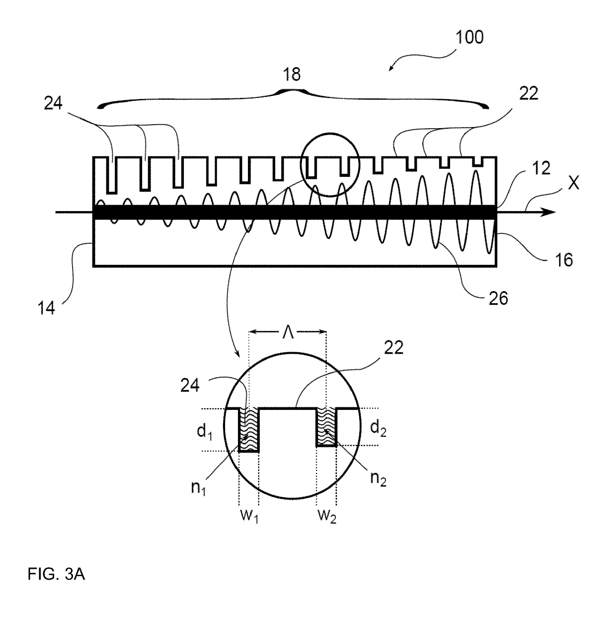
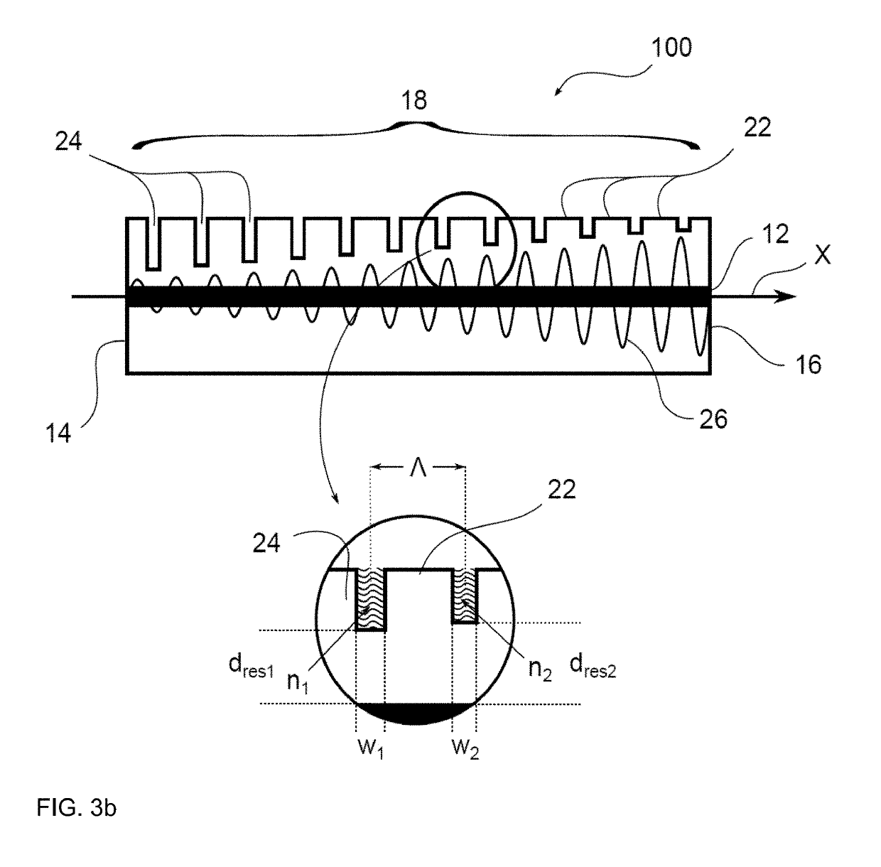
This adaptation enables improved thermal stability and extended thermal tuning range without compromising electro-optical power increase, enhancing the performance of high-power laser diodes by reducing the influence of manufacturing tolerances and optimizing the interaction between the wave and the grating.

Problems solved by technology

However, such a strongly interacting grating reduces the efficiency of the outcoupling and increases the optical losses within the resonator.
In the design of laser diodes with distributed feedback, the influence of the grating must be kept as low as possible, since even a small increase in the electrical resistance of the current path or the occurring optical absorption can often lead to a collapse of the laser performance.
However, in the production of laser diodes with distributed feedback based on such high-order gratings, the allowable manufacturing tolerances for the necessary grating depth generation are extremely small.
In the case of uniform gratings, however, the parameter ranges are generally already completely exhausted and largely optimized, so that a further improvement of the thermal tuning behavior can only be achieved at the expense of the conversion efficiency or outcoupling efficiency of the laser diode.

Method used


Image

  • Laser diode with distributed feedback and method for producing
  • Laser diode with distributed feedback and method for producing
  • Laser diode with distributed feedback and method for producing

Examples


Embodiment Construction

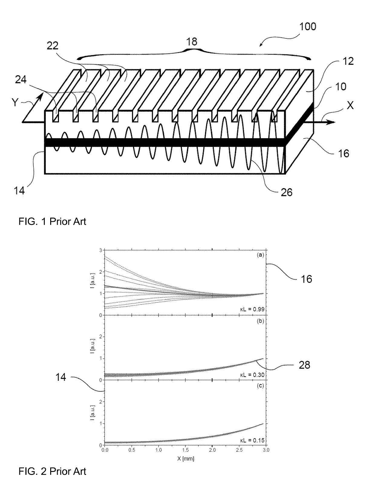
[0061]FIG. 1 shows a spatially schematic representation of a laser diode 100 with distributed feedback according to the prior art. An active layer 10 is enclosed at the top and bottom by a directly adjacent waveguiding region 12. The generation and propagation of the laser radiation preferably takes place along a first axis X (simultaneously the optical axis). For this purpose, a second axis Y extends parallel to the active layer 10. The edges of the laser diode 100 pierced by the first axis X form a rear facet 14 and a front facet 16. In this case, the laser radiation generated in the laser diode 100 exits via the front facet 16. This can be provided with an additionally applied antireflection coating. The rear facet 14, however, is often provided with a mirror coating to suppress outcoupling. During operation of the laser diode, a wave 26 builds up between the front facet 16 and the rear facet 14, which is guided through the waveguiding region 12 along the first axis X. Within the...


PUM


Abstract

Laser diode comprises an active layer; a waveguiding region at least partially surrounding the active layer; a rear facet; a front facet designed for outcoupling laser radiation, wherein the active layer extends at least partially along a first axis (X) between the rear facet and the front facet; and a grating operatively connected to the waveguiding region, wherein the grating comprises a plurality of bridges and trenches designed such that an average increase of a coupling parameter P for the plurality of trenches along the grating is non-zero, wherein the coupling parameter P of a trench is defined by the equation, wherein dres is a distance of the trench to the active layer, w is a width of the trench and Δn is the refractive index difference between a refractive index of the trench and a refractive index of a material surrounding the trench.

Description

[0001]This application is the U.S. National Stage of International Application No. PCT / EP2016 / 055019, filed Mar. 9, 2016, which claims foreign priority benefit under 35 U.S.C. § 119 of German Application No. 10 2015 110 515.2 filed Jun. 30, 2015.[0002]The invention relates to a laser diode with distributed feedback and a method for producing. In particular, the present invention relates to a laser diode and a method for producing in which the distributed feedback occurs via a surface grating of high order while radiation is decoupled preferably on one side and in which the coupling strength of the grating is adapted to the power density of the wave guided in the laser diode.TECHNOLOGICAL BACKGROUND OF THE INVENTION[0003]Laser diodes with distributed feedback (also referred to as distributed feedback or DFB laser diodes) are monolithic constructed frequency stabilized laser light sources. In contrast to diode lasers with an external cavity or DBR (Distributed Bragg Reflector) laser d...

Claims


Application Information

Patent Timeline
Patent Type & Authority Patents(United States)
IPC IPC(8): H01S5/12H01S5/20H01S5/026
CPCH01S5/1225H01S5/026H01S5/2086H01S5/1231H01S5/1221
Inventor FRICKE, JORGERBERT, GOTZCRUMP, PAULDECKER, JONATHAN
Owner FERDINAND BRAUN INST GGMBH LEIBNIZ INST FUR HOCHSTFREQUENZTECHNIK
Learn More