Pacemaker system equipped with a flexible intercostal generator

a generator and intercostal technology, applied in the field of cardiac surgery, can solve the problems of pneumothorax, lead fracture, dislocation,

Active Publication Date: 2019-12-10
HAKKI A HAMID +1
View PDF74 Cites 0 Cited by
  • Summary
  • Abstract
  • Description
  • Claims
  • Application Information

AI Technical Summary

Benefits of technology

[0081]The generator's electrodes transmit data to the microprocessor to confirm the presence of the non life-threatening

Problems solved by technology

Without the electrodes, generators are unable to detect electrical cardiac activity.
However, complications arise in a large percentage of patients which are directly related to the use of the electrical generator or the transvenous lead wire system.
These problems are usually associated with infection, pocket hematoma, pneumothorax, lead fracture, dislodgement, and vascular access limitations.
Single chamber ventricular systems are generally limited to patients with atrial fibrillation and slow ventricular response which do not require frequent pacing.
Frequent ventricular apical pacing has been shown to be deleterious to cardiac function.
Unfortunately, the device is relatively bulky (having the volume of about 33 ml).
Recharging of implanted devices (such as artificial heart and cardio pacemakers) remains a serious problem in the field of cardiology.
Such conventional generators are generally disk-shaped and may not be suitable for operability in close proximity to cardiac structures.
The systems described in the above-referenced U.S. Patents are prone to problems due to frequent charging.
Specifically, these pacemakers may suffer from memory effects that can lead to reduction of the battery capacity exponentially after each recharge, as well as poor specific energy density, low cell voltage and liberation of hydrogen gas.
The inappropriate electric shocks constitut

Method used


Image

  • Pacemaker system equipped with a flexible intercostal generator
  • Pacemaker system equipped with a flexible intercostal generator
  • Pacemaker system equipped with a flexible intercostal generator

Examples


Embodiment Construction

)

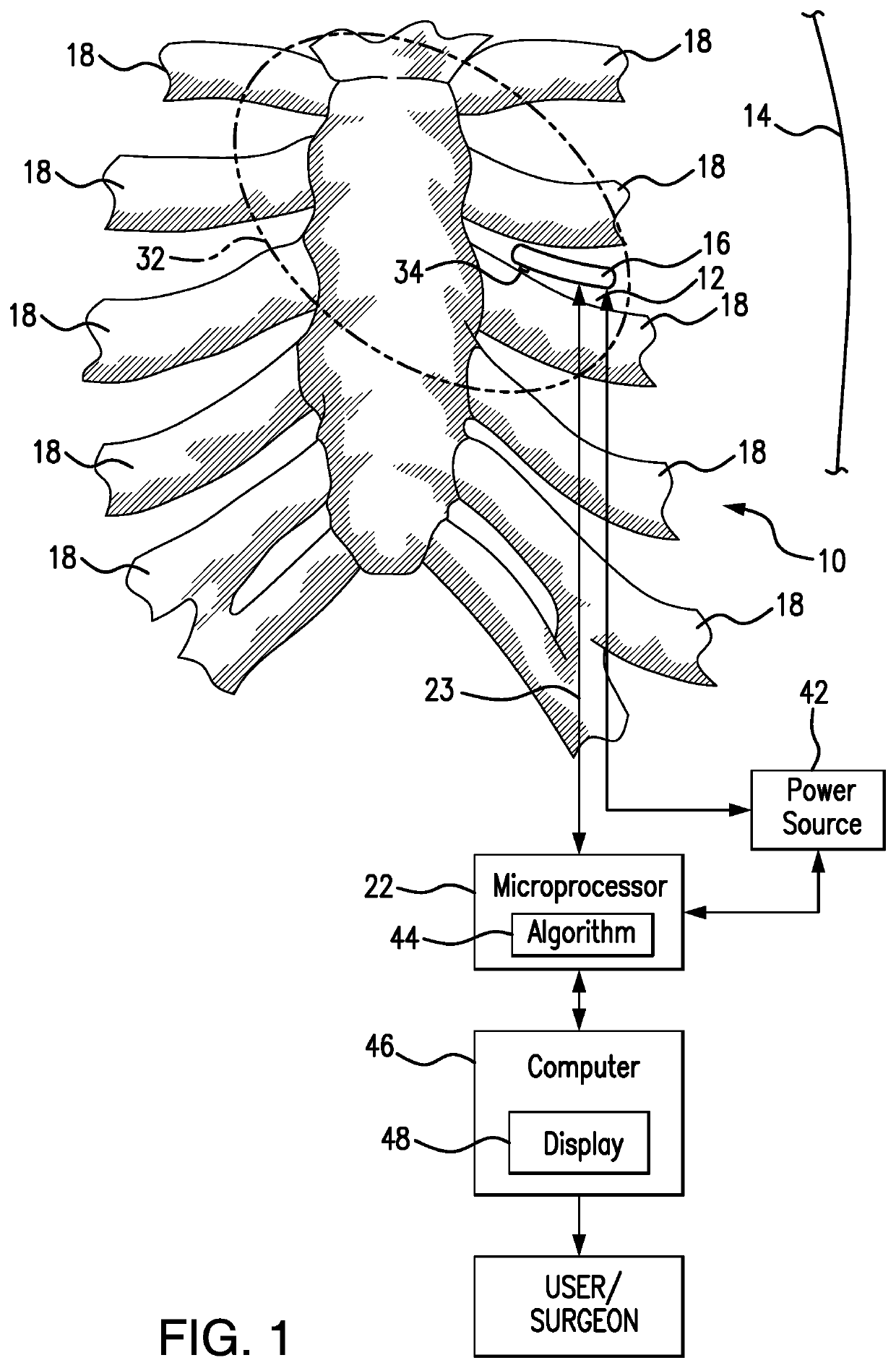
[0122]Referring now to FIGS. 1-4, a pacemaker system 10 is designed for generating electrical, acoustic (ultrasound, Doppler), infrared, and magnetic energy directed to a mammalian tissue and sensing such energy from the tissue of interest. The intercostal space 12 of a patient's chest wall 14 is selected as an implantation site in order to avoid interference from bony structures, such as ribs. The intercostal space location, specifically, the fourth or fifth intercostal space, is positioned in close proximity to the heart of a patient without intervening lung tissue (that otherwise may interfere with electromagnetic or ultrasonic signals traveling to and from the heart).

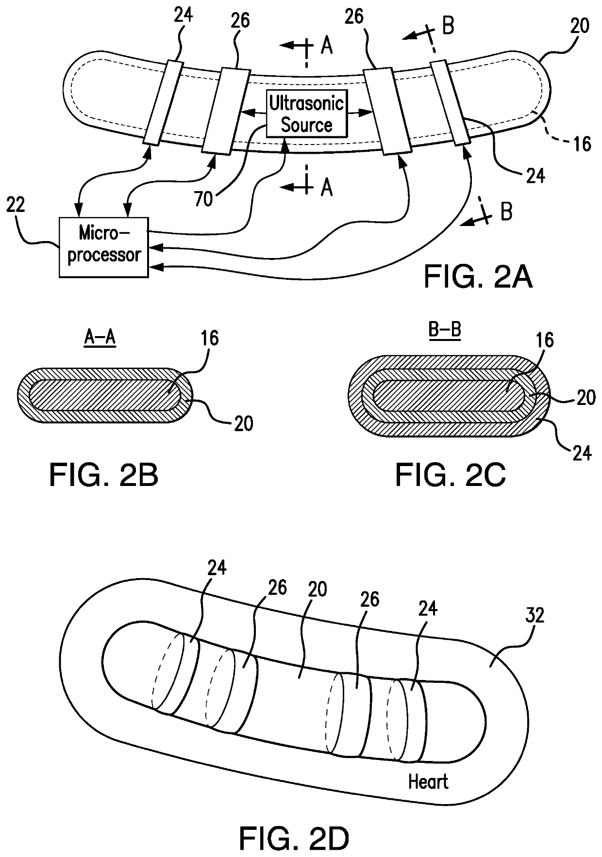
[0123]The subject system 10 includes a pacemaker generator 16 adapted to be received within the body of a patient, and particularly, in the intercostal region 12 located between patient ribs 18. The generator 16 is formed as a flexible elongated low-profile (near-flat)member applicable to dynamically changing sites...


PUM


Abstract

A pacemaker system is configured to sense electrical and mechanical activity of the heart tissue within a mammalian body and to generate a corresponding signal responsive to the sensed cardiac activity. The system includes a flexible electrical generator that contains EKG (ECG) electrodes for measuring electrical activity and ECHO piezoelectric electrodes for measuring mechanical activity of the heart and Doppler blood flow. The generator is embedded in a flexible shield, and is contoured to conform to the anatomy of the intercostal space to be embedded between the ribs of a patient and in the position overlying the heart. The system provides for pacing as well as defibrillation, responsive to the readings of the heart activities. A microprocessor analyzes a cardiac situation, based on the sensor's readings, produces a diagnosis, and generates control signals, such as “pacing pulse” in a life-threatening situation, or “observe” in a non life-threatening situation.

Description

REFERENCE TO RELATED APPLICATIONS[0001]This application is a Continuation-in-Part of patent application Ser. No. 15 / 042,301 filed on 12 Feb. 2016 which is a Continuation-in-Part of patent application Ser. No. 13 / 649,792 filed on 11 Oct. 2012, now U.S. Pat. No. 9,289,593 and issued on 22 Mar. 2016, which was based on Provisional Patent Application Ser. No. 61 / 545,913 filed on 11 Oct. 2011.INCORPORATION BY REFERENCE[0002]patent application Ser. No. 15 / 042,301; patent application Ser. No. 13 / 649,792 and Provisional Patent Application Ser. No. 61 / 545,913 are hereby incorporated by reference.FIELD OF THE INVENTION[0003]The present invention relates to the field of cardiology, and in particular, to implantable pacemaker systems.[0004]More in particular, the present invention is directed to treatment of symptomatic bradycardia using a subcutaneous generator surgically implanted in the intercostal space in proximity to the heart of a patient to provide electrical cardiac pacing which does n...

Claims


Application Information

Patent Timeline
IPC IPC(8): A61N1/36A61N7/00A61N1/05A61N1/362
CPCA61N7/00A61N1/362A61N1/057A61N1/0504A61N1/0587A61N1/36031A61N1/3756A61N1/3787A61N1/3956A61N1/39622A61N2007/0026A61N2007/0052
Inventor HAKKI, A-HAMIDHAKKI, A-HADI
Owner HAKKI A HAMID
Why Eureka
Try Eureka