
Group and method for measuring the pressure in closed containers

Active Publication Date: 2020-02-25
FT SYST
View PDF18 Cites 0 Cited by
  • Summary
  • Abstract
  • Description
  • Claims
  • Application Information

AI Technical Summary

Benefits of technology

The patent describes a method for measuring gases by using a sub-element to weigh the measurements of multiple signals. This allows for more accurate and accurate measurement of the gas inside a container. The method also involves measuring the gas in a direct way without a container to remove external influences. The weighting of the direct measurement is done based on the size of the space above the gas and the length of the optical path travelled by the laser beam. Overall, this method provides a better way to measure gases in containers.

Problems solved by technology

These machines, as well as being bulky and having a significant impact on the production lines, are influenced by the operating plant conditions.
Such a technique is, however, influenced by the repetitiveness of the closures, i.e., for the same internal pressure, there could be a difference in the measurement of the acoustic response in the case in which the closures carried out are not perfectly identical.
The Applicant has found that laser spectroscopy measuring apparatuses known in the state of the art are difficult to use to directly measure, on line, the internal pressure of commercial containers, like for example bottles.
Such containers are characterised both by poor optical quality that leads to an even substantial attenuation of the laser beam, and by dishomogeneity of such walls that contributes to high diffusion of the light and retroreflection of the radiation.
The Applicant has, indeed, observed that, since the laser light is strongly coherent, every contribution of reflected / diffused light causes etalon disturbances, i.e. spurious and variable modulations of the intensity due to the interference between coherent beams.
Such disturbances are often the limiting element to the precision with which a measurement can be carried out directly in line according to laser spectroscopy technology in commercial containers.
The Applicant has also found that laser spectroscopy measurers according to the state of the art do not allow operation at the high speeds of forward motion characteristic of filling and / or packaging plants of foods or beverages.
In this way, the data measurement contributions from scans that are not useful tend to have a low influence on the overall measurement.
In particular, the systems used up to now for determining the signal acquisition time period cannot be used at the characteristic speeds of filling and / or packaging plants of beverages or foods.
However, the calculation offered by the encoder is not able to provide a precise indication since the forward motion system can undergo delays with respect to the reference of the encoder or even the container could not be firmly constrained to the forward motion system and therefore undergo displacements during the conveying.
Similarly, not even the addition of photocells is sufficient to offer the level of precision necessary in use at the characteristic speeds of filling and / or packaging plants of beverages or foods.
This leads to a partial elimination of the gas flushed at the inspection area, due to the movement of the containers, and therefore to incomplete elimination of the gas under examination in such an area.
For example, in the measurement of pressure inside glass bottles filled with beer, where the laser spectroscopy technique reveals the total and partial pressure of carbon dioxide, there are great distortions on the signal acquired caused by possible deformations of the glass or by the presence of foam in the product.
Similarly, in the measurement of pressure inside plastic bottles filled with still water, where the laser spectroscopy technique reveals the total pressure through scanning on the absorption line of water vapour, the presence of a droplet of nitrogen in the top space, used to increase the total pressure of the sealed bottle, causes great distortions of the detected signal (very variable presence of state of condensation as a function of the time passed since the nitrogen was inserted and the amount thereof).
A low signal amplitude is, indeed, usually due to disturbance factors such as the presence of external or internal droplets, defects in the wall of the container, the presence of a tab that allows the product to be opened present in certain types of containers and so on.

Method used


Image

  • Group and method for measuring the pressure in closed containers
  • Group and method for measuring the pressure in closed containers
  • Group and method for measuring the pressure in closed containers

Examples


Embodiment Construction

In the following description, for the illustration of the figures, identical reference numerals will be used to indicate constructive elements with the same function. Moreover, for the sake of clarity of illustration, some reference numerals are not repeated in all of the figures.

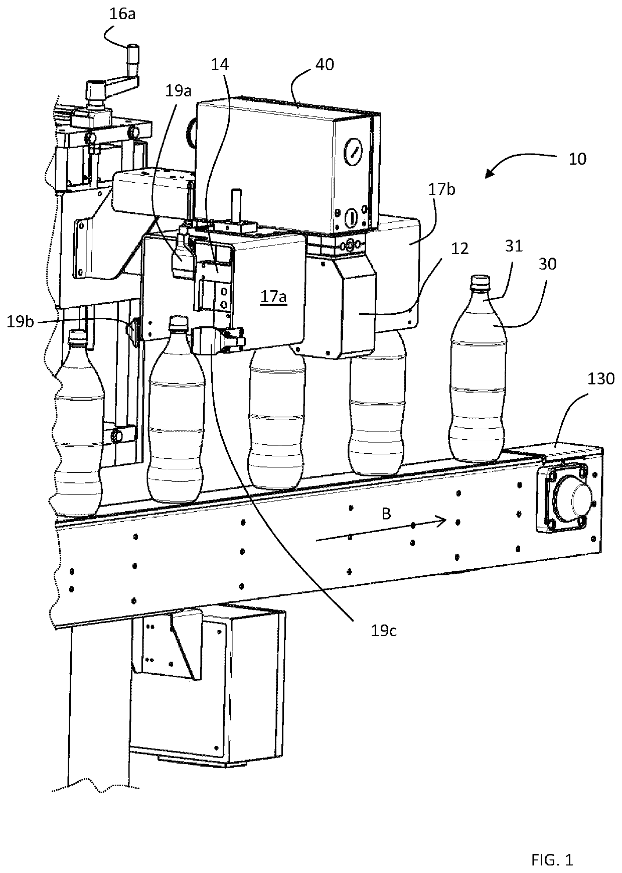
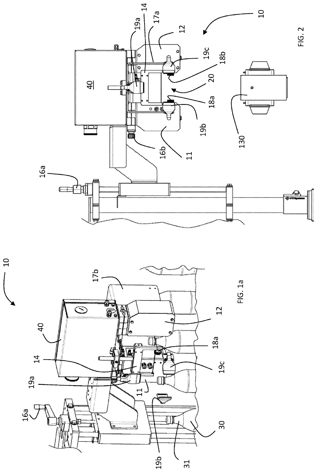
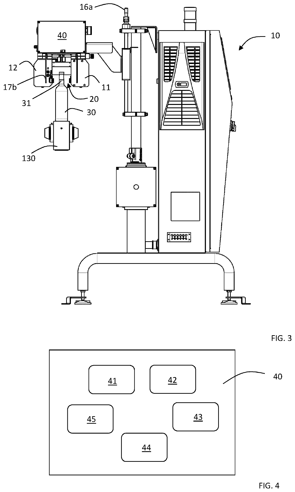
With reference to the figures, a group for measuring the pressure in closed containers is shown, wholly indicated with 10.

In the present description and in the subsequent claims, it is presumed that the closed containers 30 subjected to checking are made from optically transparent material at least at a portion of its top space 31.

As shown in FIG. 1, the measuring group 10 comprises a laser source 11 having an optical axis A for emitting a laser beam and a detector 12 facing the laser source 11 so as to detect at least one portion of the laser beam emitted by the source 11.

In the space located between the laser source 11 and the detector 12 there is an inspection area 20 adapted for the passage of at least ...


PUM


Abstract

A group and method for measuring the pressure in closed containers made from optically transparent material at least at a portion of a top space without contacting the containers, and a filling and / or packaging plant using the measuring group. The measuring group comprises an inspection area; a laser source with optical axis for the emission of a laser beam at a wavelength tunable with an absorption wavelength of a gas contained in a container top space; at least one detector to detect the laser beam once it has travelled through the inspection area to provide an absorption spectrum of said gas; a device for detecting the signal acquisition time period corresponding to the passage of a top space through the inspection area; having means for identifying signal contributions useful for the pressure measurement amongst the data representative of an absorption spectrum acquired during the signal acquisition time period.

Description

FIELD OF THE INVENTIONThe present invention concerns a group and a method for measuring the pressure in closed containers, as well as an automatic filling and / or packaging plant using such a group.In particular the present invention concerns a group and a method for contactlessly measuring the pressure in closed containers, able to be used directly in automatic filling and / or packaging plants operating at high speed, without the need to stop or slow down such plants.In the present description, the expression “directly measures in line” is meant to indicate the possibility of carrying out the measurement on the containers without the need to take them from the line beforehand.The invention concerns a group and a method for measuring the total and / or partial pressure in closed containers at least partially made from optically transparent material, in particular plastic or glass material, like for example but not exclusively bottles of wine, beer, water, fizzy and still drinks, contain...

Claims


Application Information

Patent Timeline
IPC IPC(8): G01L11/02G01L19/00G01M3/38G01N21/39G01M3/32B67C3/22B67C7/00G01N21/90
CPCG01L11/02G01M3/38B67C3/22G01L19/0092B67C7/0026G01M3/3272G01N21/39G01N21/90
Inventor FORESTELLI, FABIOFEDEL, MASSIMO
Owner FT SYST
Learn More