Thermal management of RF devices using embedded microjet arrays

a technology of micro-jet arrays and thermal management, which is applied in the direction of indirect heat exchangers, laminated elements, lighting and heating apparatus, etc., can solve the problems of limited heat transfer from the maximum component temperature of the application of the heat generating device, and the significant amount of heat generated, etc., to achieve the effect of increasing single-phase heat transfer, improving heat transfer properties, and increasing contact area

Active Publication Date: 2020-05-12
MASSACHUSETTS INST OF TECH
View PDF54 Cites 8 Cited by
  • Summary
  • Abstract
  • Description
  • Claims
  • Application Information

AI Technical Summary

Benefits of technology

[0011]The present invention generally relates to a microjet array for use as a thermal management system for a heat generating device, such as an RF device. The microjet array is formed in a jet plate, which is attached directly to the substrate containing the heat generating device. Additional enhancing features are used to further improve the heat transfer coefficient above that inherently achieved by the array. Some of these enhancements may also have other functions, such as adding mechanical structure, electrical connectivity or pathways for waveguides. This technology enables higher duty cycles, higher power levels, increased component lifetime, and / or improved SWaP for RF devices operating in airborne, naval (surface and undersea), ground, and space environments. This technology serves as a replacement for existing RF device thermal management solutions, such as high-SWaP finned heat sinks and cold plates.
[0013]According to another embodiment, a method of cooling a semiconductor component is disclosed. The method comprises directing a single-phase coolant fluid through a plurality of microjets toward a surface of the semiconductor component such that the single-phase coolant fluid strikes an impingement surface; and exhausting the single-phase coolant fluid through an exhaust port away from the semiconductor component after the single-phase coolant fluid strikes the impingement surface. In certain embodiments, the method further comprises controlling the flow of effluent toward the exhaust port. In some embodiments, the effluent is routed so as to avoid an impingement surface of an adjacent microjet. In certain embodiments, the heat transfer properties are improved. In certain embodiment, the surface area of the impingement surface is increased to increase contact between the semiconductor component and the single-phase coolant fluid. In certain embodiments, wall jet features that extend perpendicular to the impingement surface are provided to increase single-phase heat transfer by boundary layer suppression and also increase contact area.

Problems solved by technology

Many electronic components, such as processing units, and radio frequency (RF) devices, are commonly used in many of today's circuits and generate significant amounts of heat.
A limiting factor in many of these applications is the maximum component temperature of the heat generating device, which may occur, for example, within the gate region of a HEMT.
Thus, the heat transfer from the heat generating device can be limited by the performance of these technologies.
The thermal interface material, even if chosen to have low resistance, still reduces the efficiency of any solution.
Further, the size, weight, and power (SWaP) of existing thermal management solutions often drives the design of these systems and can limit their performance.
For example, the system in which the heat generating device is contained may be compact, limiting the ability to transfer the heat to a cooler ambient location.

Method used


Image

  • Thermal management of RF devices using embedded microjet arrays
  • Thermal management of RF devices using embedded microjet arrays
  • Thermal management of RF devices using embedded microjet arrays

Examples


Embodiment Construction

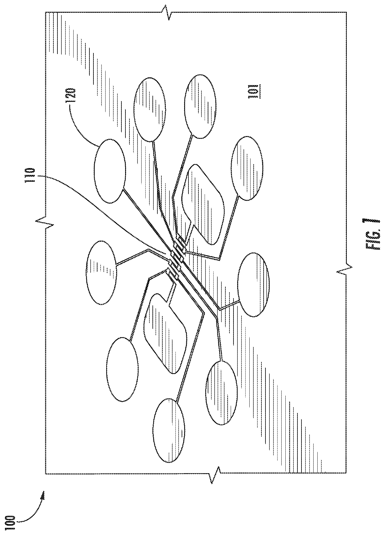
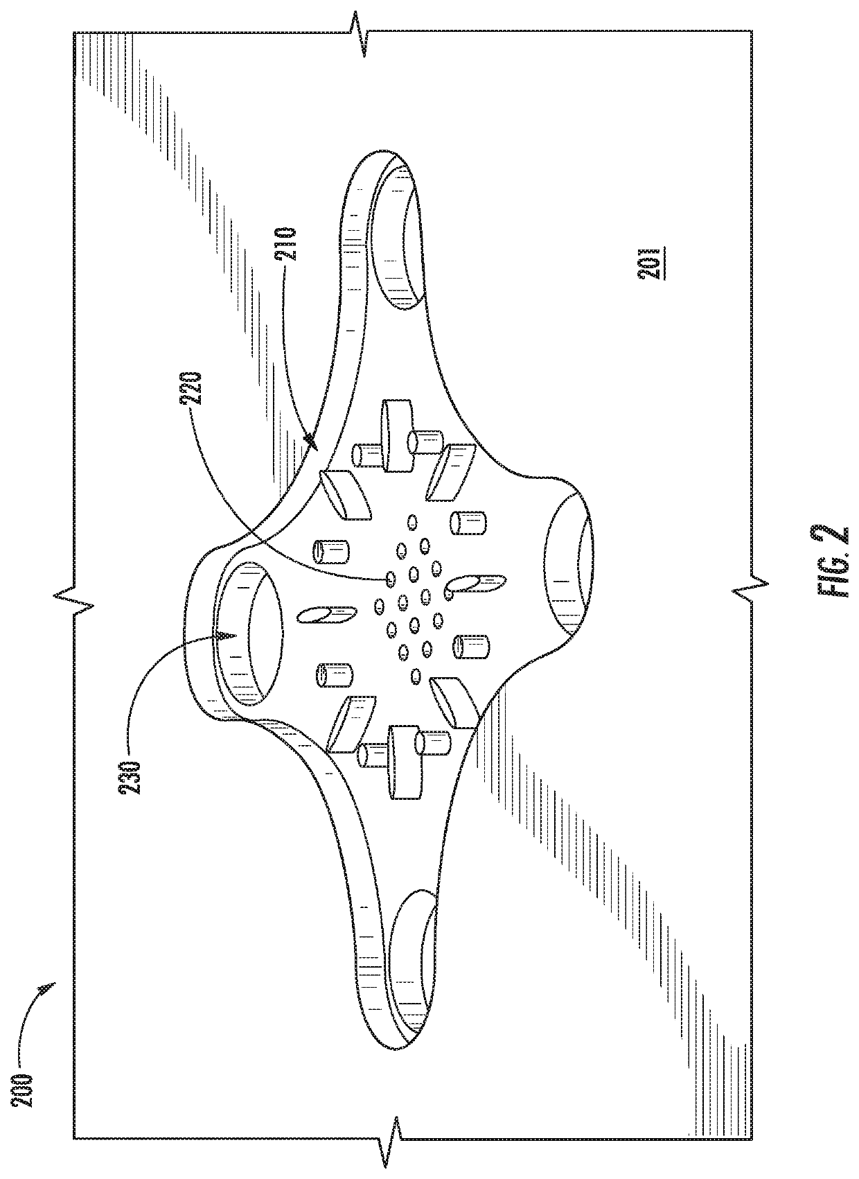
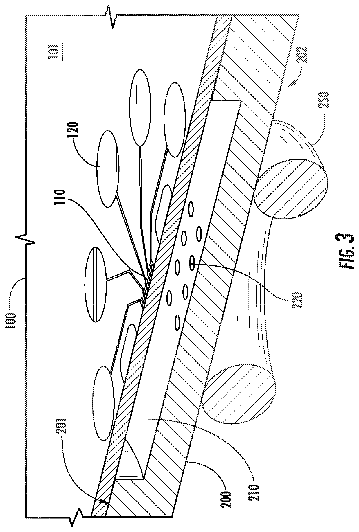
[0031]Microjet impingement is a heat transfer technique by which a jet or an array of jets impinge onto a surface for the purpose of transferring heat between the surface and the fluid of the jet. Jets can be formed by the use of nozzles, tubes or an orifice plate and are characterized by having a substantially higher momentum in one direction than the surrounding fluid. Typically, a turbulent jet exit velocity profile is flat across the radius, reducing to zero at the edge due to the presence of the nozzle. This high velocity jet suppresses the thermal boundary layer at the heat transfer surface resulting in high heat transfer coefficients.

[0032]Adjacent fluid, particularly if it is the same fluid, is entrained into the core of the jet, spreading the momentum of the jet out to a larger and larger radius as the jet propagates downstream. At the point where the centerline of the jet meets the impingement surface, a stagnation point exists due to symmetry. Near this point, the flow tu...


PUM


Abstract

The present invention generally relates to a microjet array for use as a thermal management system for a heat generating device, such as an RF device. The microjet array is formed in a jet plate, which is attached directly to the substrate containing the heat generating device. Additional enhancing features are used to further improve the heat transfer coefficient above that inherently achieved by the array. Some of these enhancements may also have other functions, such as adding mechanical structure, electrical connectivity or pathways for waveguides. This technology enables higher duty cycles, higher power levels, increased component lifetime, and / or improved SWaP for RF devices operating in airborne, naval (surface and undersea), ground, and space environments. This technology serves as a replacement for existing RF device thermal management solutions, such as high-SWaP finned heat sinks and cold plates.

Description

[0001]This application claims priority to U.S. Provisional Application Ser. No. 62 / 415,704, filed Nov. 1, 2016 and U.S. Provisional Application Ser. No. 62 / 415,739, filed Nov. 1, 2016, the disclosures of which are incorporated by reference in their entireties.[0002]This invention was made with Government support under Contract No. FA8721-05-C-0002 awarded by the U.S. Air Force. The Government has certain rights in the invention.BACKGROUND OF THE INVENTION[0003]Many electronic components, such as processing units, and radio frequency (RF) devices, are commonly used in many of today's circuits and generate significant amounts of heat. For example, RF devices, such as high electron mobility transistors (HEMTs), are commonly used in radar (aircraft surveillance, weather surveillance, tactical); electronic warfare (EW), including jamming; RF communication systems; and other applications. Processing units, such as CPUs, are commonly used in computers, laptops, mobile electronics, and othe...

Claims


Application Information

Patent Timeline
Patent Type & Authority Patents(United States)
IPC IPC(8): H01L23/473H01L21/48F28F13/06H05K7/20F28D1/02F28F3/12
CPCH01L21/4871F28D1/0246H05K7/20254H01L23/4735F28F13/06F28F3/12F28F2260/02Y10S165/908
Inventor MALOUIN, JR., BERNARD A.SMITH, JAMES PAULBROWNE, ERIC A.
Owner MASSACHUSETTS INST OF TECH
Why Eureka
Try Eureka