Engine system

a technology of engine system and intake passage, which is applied in the direction of engines, mechanical equipment, machines/engines, etc., can solve the problems of excessive temperature of the compressor, low wall temperature of the intake passage downstream of the compressor, and excessive heating of the compressor, so as to facilitate the transfer of heat, facilitate the warm-up of the compressor, and increase the wall temperature

Active Publication Date: 2020-05-19
TOYOTA JIDOSHA KK
View PDF26 Cites 1 Cited by
  • Summary
  • Abstract
  • Description
  • Claims
  • Application Information

AI Technical Summary

Benefits of technology

[0006]The disclosure provides a controller for an internal combustion engine, which, in the case where a water-cooled compressor is employed, achieves both a reduction in production of condensed water in an intake passage downstream of the compressor and a reduction in accumulation of a deposit in an intake passage inside the compressor and downstream of the compressor.
[0014]With above-described configuration, during the predetermined period from the beginning of cold start of the internal combustion engine, the flow rate of low-temperature coolant that flows through the low-temperature coolant circulation loop is increased as compared to the flow rate after the predetermined period. Thus, in comparison with the case where such an increase in the flow rate is not performed, it is possible to facilitate transfer of heat from high-temperature coolant to low-temperature coolant via intake air inside the intercooler during the predetermined period. Thus, it is possible to advance an increase in the temperature of low-temperature coolant, so the warm-up of the compressor is facilitated as compared to a comparative configuration that utilizes the low-temperature coolant circulation loop that does not utilizes the heat of high-temperature coolant. As a result, the outlet gas temperature of the compressor increases, so it is possible to early increase the wall temperature of the intake passage downstream of the compressor. Therefore, it is possible to reduce production of condensed water in the intake passage downstream of the compressor. The low-temperature coolant circulation loop receives heat supplied from high-temperature coolant via intake air inside the intercooler; however, the low-temperature coolant circulation loop is basically a circulation loop for low-temperature coolant, and is not intended to cool the water jacket of the internal combustion engine. For this reason, even when high-load operation is performed, the temperature of low-temperature coolant that is introduced into the compressor is lower than the temperature of high-temperature coolant during equivalent high-load operation in the comparative configuration in which high-temperature coolant is introduced into the in-compressor passage. Therefore, the configuration according to the present embodiment is superior to the comparative configuration from the viewpoint of reducing accumulation of deposit in the intake passage inside the compressor and downstream of the compressor. As described above, according to the aspect of the disclosure, when a water-cooled compressor is employed, both a reduction in production of condensed water in the intake passage downstream of the compressor and a reduction in accumulation of deposit in the intake passage inside the compressor and downstream of the compressor are achieved.

Problems solved by technology

As a result, the wall temperature of an intake passage downstream of the compressor is low.
As a result, there is a concern that the moisture condenses and condensed water is produced.
However, if high-temperature coolant is utilized, there is a concern that the temperature of the compressor excessively increases at the time when the internal combustion engine is operated at a high load.
As a result, there is a concern that HC components accumulate as a deposit on the wall face of the intake passage inside the compressor and the wall face of the intake passage downstream of the compressor.
The low-temperature coolant circulation loop receives heat supplied from high-temperature coolant via intake air inside the intercooler; however, the low-temperature coolant circulation loop is basically a circulation loop for low-temperature coolant, and is not intended to cool the water jacket of the internal combustion engine.

Method used


Image

  • Engine system
  • Engine system
  • Engine system

Examples


first embodiment

[0026]the disclosure will be described with reference to FIG. 1 to FIG. 6.

Description of System Configuration of First Embodiment

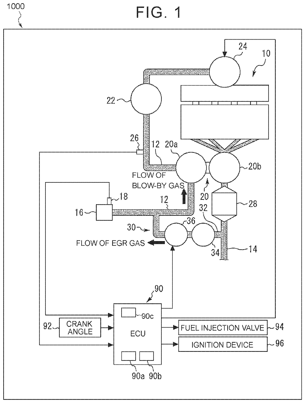
[0027]FIG. 1 is a view that schematically shows an example of the configuration of a system according to the first embodiment of the disclosure. The system shown in FIG. 1 includes an internal combustion engine (spark ignition engine as an example) 10. An intake passage 12 and an exhaust passage 14 communicably connected to each cylinder of the internal combustion engine 10.

[0028]An air cleaner 16 is connected near the inlet of the intake passage 12. An air flow sensor 18 is provided in the air cleaner 16. The air flow sensor 18 outputs a signal corresponding to the flow rate of air that is taken into the intake passage 12. A compressor 20a of a turbocharger 20 is arranged downstream of the air cleaner 16. On the other hand, a turbine 20b of the turbocharger 20 is arranged in the exhaust passage 14. The compressor 20a is of a water-cooled type. The detaile...

second embodiment

[0069]Next, the disclosure will be described with reference to FIG. 7 to FIG. 9.

Description of System Configuration of Second Embodiment

[0070]The system according to the present embodiment includes an internal combustion engine that is different from the internal combustion engine 10 in that an LT coolant circulation loop 100 shown in FIG. 7 is provided instead of the LT coolant circulation loop 60. The system according to the present embodiment is the same as that of the first embodiment in that temperature control is executed by using the LT thermostat 76 in order to bring the temperature of LT coolant close to the predetermined target temperature.

[0071]FIG. 7 is a view that schematically shows an example of the configuration of passages of an LT coolant circulation loop 100 according to the second embodiment of the disclosure. In FIG. 7, the HT coolant circulation loop 40 is not shown except part of the HT coolant circulation loop 40. In FIG. 7, like reference numerals denote the...


PUM


Abstract

An engine system includes an internal combustion engine, a compressor, a high-temperature coolant circulation circuit, a low-temperature coolant circulation circuit, an intercooler, and an electronic control unit. The intercooler is configured to transfer heat of the high-temperature coolant to the low-temperature coolant via intake air. An in-compressor passage of the compressor is arranged in the low-temperature coolant circulation circuit at a location at which the low-temperature coolant that exits from an in-cooler low-temperature water passage during a predetermined period from beginning of cold start is introduced into the in-compressor passage without passing through a low-temperature radiator. The electronic control unit is configured to increase the flow rate of the low-temperature coolant that flows through the low-temperature coolant circulation circuit during the predetermined period as compared to the flow rate after the predetermined period.

Description

INCORPORATION BY REFERENCE[0001]The disclosure of Japanese Patent Application No. 2016-251012 filed on Dec. 26, 2016 including the specification, drawings and abstract is incorporated herein by reference in its entirety.BACKGROUND1. Technical Field[0002]The disclosure relates to an engine system and, more particularly, to an engine system including a water-cooled compressor that supercharges intake air.2. Description of Related Art[0003]For example, Japanese Patent Application Publication No. 2014-122582 (JP 2014-122582 A) describes a turbocharger including a compressor that supercharges intake air into an internal combustion engine. The housing of the compressor has a coolant passage for cooling the compressor.SUMMARY[0004]In an internal combustion engine including a compressor that supercharges intake air, at least one of EGR gas and blow-by gas can be introduced into an intake passage upstream of the compressor. In the early stage after the beginning of cold start, an intake air ...

Claims


Application Information

Patent Timeline
Patent Type & Authority Patents(United States)
IPC IPC(8): F02B29/04F02M26/21F01P5/10F01P5/12F01P3/18F01P7/14F01P7/16F02M26/06
CPCF01P5/10F02B29/0443F02M26/21F01P7/167F01P7/16F02M26/06F01P2007/146Y02T10/146F01P2060/02F01P2060/12F01P2005/105F01P2003/182Y02T10/12
Inventor KAKUTA, YUSHI
Owner TOYOTA JIDOSHA KK
Why Eureka
Try Eureka