Optical sensor device
a sensor device and optical sensor technology, applied in the field of optical sensor devices, can solve the problems of inability to recognize the naked eye, bad influence on the human body, skin or eyes, etc., and achieve the effect of low cost and high productivity
- Summary
- Abstract
- Description
- Claims
- Application Information
AI Technical Summary
Benefits of technology
Problems solved by technology
Method used
Image
Examples
first embodiment
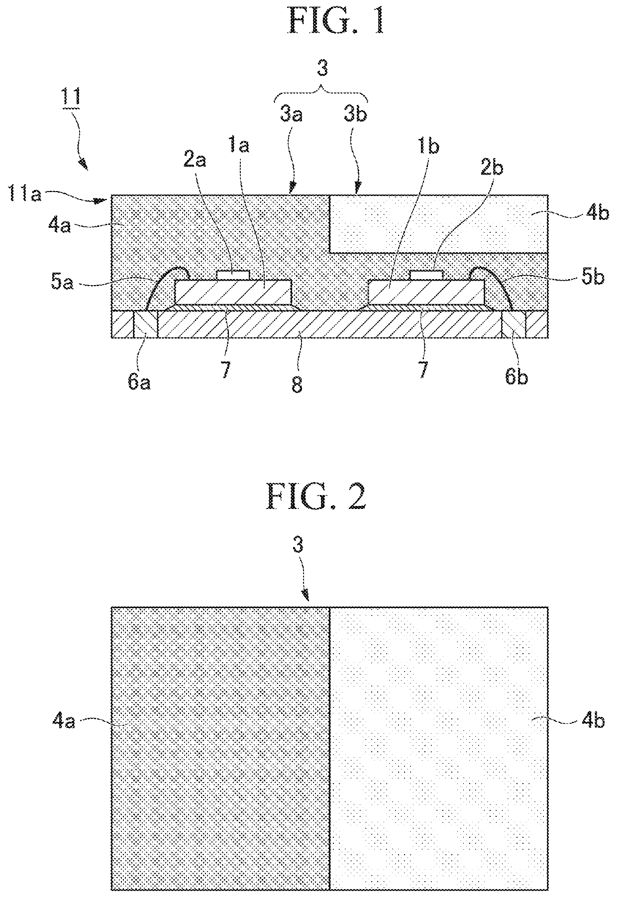
[0038]FIGS. 1 and 2 schematically show a configuration of an optical sensor device 11 according to a first embodiment. FIG. 1 is a longitudinal sectional view along a plane including two light receiving portions 2a and 2b. FIG. 2 is a top view which shows a surface on a side of a resin sealing portion 3.
[0039]An optical sensor device 11 according to the present embodiment includes a package structure 11a in which two sensor chips 1a and 1b are sealed by the resin sealing portion 3. The package structure 11a includes a first sensor chip 1a including a first light receiving portion 2a, a second sensor chip 1b including a second light receiving portion 2b, an element mounting portion 8 on which the sensor chips 1a and 1b are mounted, and the resin sealing portion 3 which seals surfaces of the sensor chips 1a and 1b and the element mounting portion 8.
[0040]The light receiving portions 2a and 2b are optical sensor elements which have sensitivity to ultraviolet light and output signals in...
second embodiment
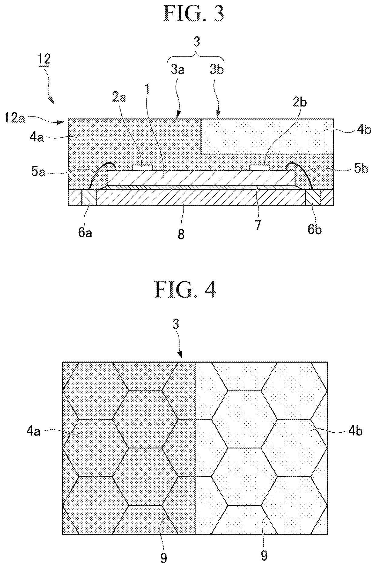
[0068]FIG. 3 schematically shows a configuration of an optical sensor device 12 according to a second embodiment of the present invention. FIG. 3 is a longitudinal sectional view of a cross section including two light receiving portions 2a and 2b. A surface on the resin sealing portion 3 side may be formed in the same manner as in FIG. 2 of the first embodiment described above. In the description of the present embodiment, the same reference numerals are given to constituent elements which are common to the first embodiment and descriptions thereof may be omitted.
[0069]The optical sensor device 12 according to the present embodiment includes a package structure 12a in which a sensor chip 1 having two light receiving portions 2a and 2b is sealed by a resin sealing portion 3. This package structure 12a includes the sensor chip 1 having a first light receiving portion 2a and a second light receiving portion 2b, an element mounting portion 8 on which the sensor chip 1 is mounted, and a ...
third embodiment
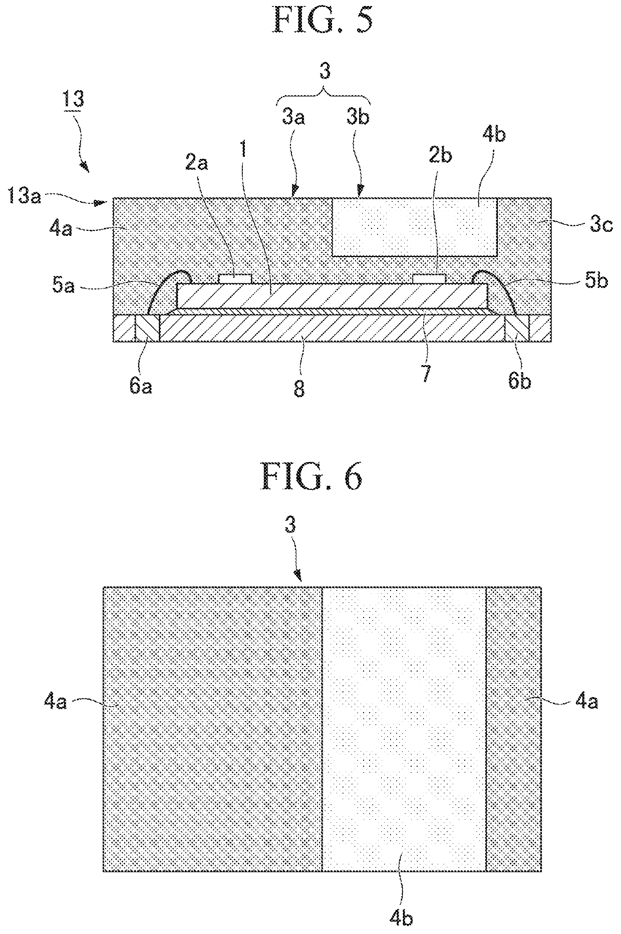
[0077]FIGS. 5 and 6 schematically show a configuration of an optical sensor device 13 according to a third embodiment of the present invention. FIG. 5 is a longitudinal sectional view when a cross section including two light receiving portions 2a and 2b is viewed. FIG. 6 is a top view which shows surfaces on the side of the resin sealing portion 3. According to the present embodiment, the same reference numerals are given to constituent elements which are common to the first embodiment or the second embodiment described above, and descriptions thereof may be omitted.
[0078]The resin sealing portion 3 according to the present embodiment has a first sealing resin 4a adhered to two light receiving portions 2a and 2b, and a second sealing resin 4b disposed to overlap the first sealing resin 4a on one side of the light receiving portion 2b, which is the same as in the first embodiment or the second embodiment. The present embodiment is different from the first embodiment or the second emb...
PUM
| Property | Measurement | Unit |
|---|---|---|
| transmittance | aaaaa | aaaaa |
| transmittance | aaaaa | aaaaa |
| transmittance | aaaaa | aaaaa |
Abstract
Description
Claims
Application Information
 - R&D
- Intellectual Property
- Life Sciences
- Materials
- Tech Scout
- Unparalleled Data Quality
- Higher Quality Content
- 60% Fewer Hallucinations
Browse by: Latest US Patents, China's latest patents, Technical Efficacy Thesaurus, Application Domain, Technology Topic, Popular Technical Reports.
© 2025 PatSnap. All rights reserved.Legal|Privacy policy|Modern Slavery Act Transparency Statement|Sitemap|About US| Contact US: help@patsnap.com


