Transmittance-variable device

a variable device and transmittance technology, applied in the direction of door/window protective devices, instruments, spectales/goggles, etc., can solve the problems of deterioration of contrast ratios (cr), and achieve high transmittance, high shielding rate, and high contrast ratio

Active Publication Date: 2021-05-11
LG CHEM LTD
View PDF35 Cites 1 Cited by
  • Summary
  • Abstract
  • Description
  • Claims
  • Application Information

AI Technical Summary

Benefits of technology

[0097]The transmittance-variable device of the present application can switch between a clear state and a black state, can exhibit high transmittance in the clear state and a high shielding rate in the black state, and can exhibit a high contrast ratio even at the inclination angle. Such a transmittance-variable device of the present application can be applied to various applications including various architectural or automotive materials which need to adjust the transmittance, or eyewear such as goggles for augmented reality experience or sports, sunglasses or helmets.Mode for Invention
[0098]Hereinafter, the transmittance-variable device of the present application will be described in detail by way of examples and comparative examples, but the scope of the present application is not limited by the following transmittance-variable device.Method for Measuring Pretilt Angle
[0099]The pretilt angle of the GH cell can be measured in the following manner. In measuring the pretilt angle of the GH cell, there are a method of measuring it for one GH cell and a method of measuring it in a double cell in which two GH cells are superposed, each of which is described below. Here, the case of the method of measuring it in the double cell is useful for the case where the first to fourth vertical alignment films have all similar pretilt angles. On the other hand, the pretilt direction can be confirmed by disposing an absorptive linear polarizer on one side of the GH cell in a state where each GH cell is horizontally oriented and measuring the transmittance while rotating the polarizer 360 degrees. For example, when the transmittance is minimized in the process of rotating the polarizer 360 degrees, the angle that is perpendicular or vertical to the absorption axis of the polarizer may be defined as the pretilt direction.
[0101]First, as shown in FIG. 6, a GH cell is arranged between a light source and a transmittance measurement sensor (for example, LCMS-200). In this state, a direction connecting the measurement sensor and the light source at the shortest distance is defined as a Y-axis, and a direction orthogonal to the Y-axis is defined as an X-axis, as indicated by a dotted line in the drawing. Then, as shown in FIG. 6, the transmittance is evaluated by the measurement sensor while rotating the GH cell and irradiating it with light from the light source. In this process, the orientation state of the GH cell can be maintained in a vertical orientation state. The pretilt angle is measured through the angle formed by the surface normal (indicated by a solid line in the drawing) of the GH cell and the Y-axis at the point where the transmittance becomes maximum when the transmittance is measured through the above process. For example, if the highest transmittance is realized when the Y-axis and the surface normal form A degrees in FIG. 6, the pretilt angle can be defined as a value obtained by subtracting A degrees from 90 degrees. Here, the A degrees is a positive number measured in a clockwise or counterclockwise direction.
[0103]Even in the case of a double cell, the pretilt angle can be measured in the same manner as above. First, as shown in FIG. 7, the double cell is disposed between a light source and a transmittance measurement sensor (for example, LCMS-200). That is, in FIG. 7, the light source is disposed on any one side of the front side (outgoing direction in the drawing) or the rear side (incoming direction in the drawing) of the first GH cell (10), the measurement sensor is disposed on the other side, and the angle (the A degrees) formed by the Y-axis (the axis connecting the light source and the measurement sensor at the shortest distance) and the surface normal of the double cell at the time when the transmittance becomes maximum is measured while rotating the double cell in the rotation direction of the drawing, and then, the value obtained by subtracting the absolute value of the angle from 90 degrees may be defined as a pretilt angle. Even in this case, the orientation of the GH cells (10, 20) can be maintained in the vertical orientation.

Problems solved by technology

However, in the case of the known transmittance-variable devices to date, there is a problem that their contrast ratios (CR) are deteriorated when they are observed in an oblique direction as above.

Method used


Image

  • Transmittance-variable device
  • Transmittance-variable device
  • Transmittance-variable device

Examples


example 1

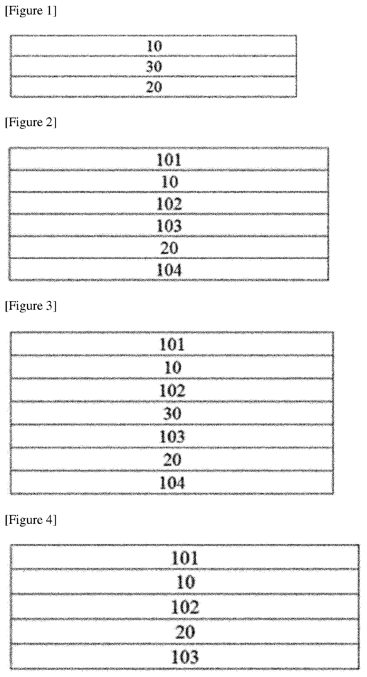
[0104]A first GH cell was produced by forming a GH layer between two COP (cycloolefin polymer) films in which an ITO (indium tin oxide) electrode layer and a vertical alignment film were sequentially formed on the surface. Here, the cell gap of the GH cell was set to about 12 μm. Here, as the vertical alignment film, an alignment film having a pretilt angle of about 89 degrees was used. The alignment film was formed to a thickness of about 200 nm by coating a polyimide-based vertical alignment film on the ITO electrode layer by bar coating, holding the film at 130° C. for about 30 minutes and rubbing the film with a rubbing cloth, and the two COP films were laminated so that the rubbing directions were equal to each other. Also, the GH layer was formed by applying a GH mixture in which nematic liquid crystals having dielectric constant anisotropy of about −4.9 and refractive index anisotropy of about 0.132 as a liquid crystal compound and a black dye having a dichroic ratio of about...

example 2

[0105]The first and second GH cells were prepared in the same manner as in Example 1, except that an isotropic (poly(ethylene terephthalate)) film in which an ITO (indium tin oxide) electrode layer and a vertical alignment film were sequentially formed on the surface and a COP (cycloolefin polymer) film in which an ITO electrode layer and a vertical alignment film were sequentially formed on the surface and the plane phase difference for light having a wavelength of 550 nm was about 137.5 nm, were applied as the substrates upon producing the GH cells, and the cell gap was about 11 μm. Upon producing the GH cell, the slow axis of the COP film was 45 degrees with the optical axis when the liquid crystal host of the GH cell was horizontally oriented. Subsequently, the transmittance-variable device was produced by attaching the COP films of the first and second GH cells such that the slow axes of the respective films were horizontal. The device is of a type in which the liquid crystal h...


PUM

PropertyMeasurementUnit
wavelengthaaaaaaaaaa
pretilt angleaaaaaaaaaa

Abstract

A transmittance-variable device is disclosed herein. In some embodiments, the transmittance-variable device includes a first guest host layer, a second guest host layer, and a phase difference element disposed between the first and second guest host layers, wherein each of the first and second guest host layers comprise a liquid crystal host and a dichroic dye guest, and the liquid crystal hosts are capable of being horizontally oriented such that their optical axes are horizontal to each other. The transmittance-variable device can switch between a clear state and a black state, can exhibit high transmittance in the clear state and a high shielding rate in the black state, and can exhibit a high contrast ratio even at the inclination angle. Such a transmittance-variable device can be used in architectural or automotive materials, or eyewear such as goggles for augmented reality experience or sports, sunglasses or helmets.

Description

CROSS-REFERENCE TO RELATED APPLICATION(S)[0001]The present application is a national phase entry under 35 U.S.C. § 371 of International Application No. PCT / KR2018 / 004780, filed on Apr. 25, 2018, claims priority from Korean Patent Application No. 10-2017-0055171, filed on Apr. 28, 2017, the disclosures of which are incorporated by reference herein.TECHNICAL FIELD[0002]This application relates to a transmittance-variable device.BACKGROUND ART[0003]A transmittance-variable device using a so-called GH cell (guest host cell), to which a mixture of a host material, which is mainly a liquid crystal compound, and a dichroic dye guest is applied, is known (for example, Patent Document 1).[0004]Such a transmittance-variable device is applied to various applications including eyewear such as sunglasses, building outer walls, vehicle sunroofs and the like. Recently, application of the transmittance-variable element to eyewear for the so-called augmented reality (AR) experience has been studied ...

Claims


Application Information

Patent Timeline
Patent Type & Authority Patents(United States)
IPC IPC(8): G02F1/137G02F1/1347C09K19/54C09K19/60G02B27/01G02C7/10G02F1/13363G02F1/1337
CPCG02F1/13475C09K19/544C09K19/60G02B27/0172G02C7/101G02F1/1337G02F1/13363G02F1/13725G02B2027/0178G02C2202/16G02F1/133746G02F2201/16G02F2202/043G02B26/00G02B26/06G02B27/01G02F1/1347G02F1/13306G02F2203/48E06B9/24B60J3/04E06B2009/2464E06B2009/2447A61F9/023G02F1/133638G02B26/007
Inventor OH, DONG HYUNLIM, EUN JUNGKIM, NAM HUN
Owner LG CHEM LTD
Why Eureka
Try Eureka