Denitration catalyst regeneration method, denitration catalyst regeneration system, and cleaning agent for denitration catalyst
a denitration catalyst and catalyst technology, applied in physical/chemical process catalysts, inorganic non-surface active detergent compositions, separation processes, etc., can solve the problems of insufficient catalytic performance after regeneration processing and reduced so as to restore catalytic performance and reduce the crushing strength of denitration catalysts. , the effect of restoring catalytic performan
- Summary
- Abstract
- Description
- Claims
- Application Information
AI Technical Summary
Benefits of technology
Problems solved by technology
Method used
Image
Examples
first embodiment
1. First Embodiment
1-1. Cleaning Agent
[0038]A cleaning agent of a first embodiment is described. The cleaning agent of the embodiment is a cleaning agent in the form of an aqueous solution which contains at least a fluorine compound and an inorganic acid.
[0039]The fluorine compound is, for example, ammonium hydrogen fluoride (NH4HF2) or an ammonium fluoride (NH4F). The fluorine compound is preferably ammonium hydrogen fluoride. The amount of ammonium hydrogen fluoride can be, for example, 1 to 10% by mass with respect to the total cleaning agent, and is preferably in the range of 1 to 5% by mass.
[0040]The inorganic acid is, for example, sulfamic acid (H3NSO3), hydrochloric acid (HCl), sulfuric acid (H2SO4), or boric acid (H3BO3). The inorganic acid is preferably hydrochloric acid, or hydrochloric acid and boric acid. Boric acid can function as a corrosion inhibitor. The amount of boric acid can be, for example, 0.001 to 10% by mass with respect to the cleaning agent. In addition, it...
second embodiment
2. Second Embodiment
2-1. Regeneration System
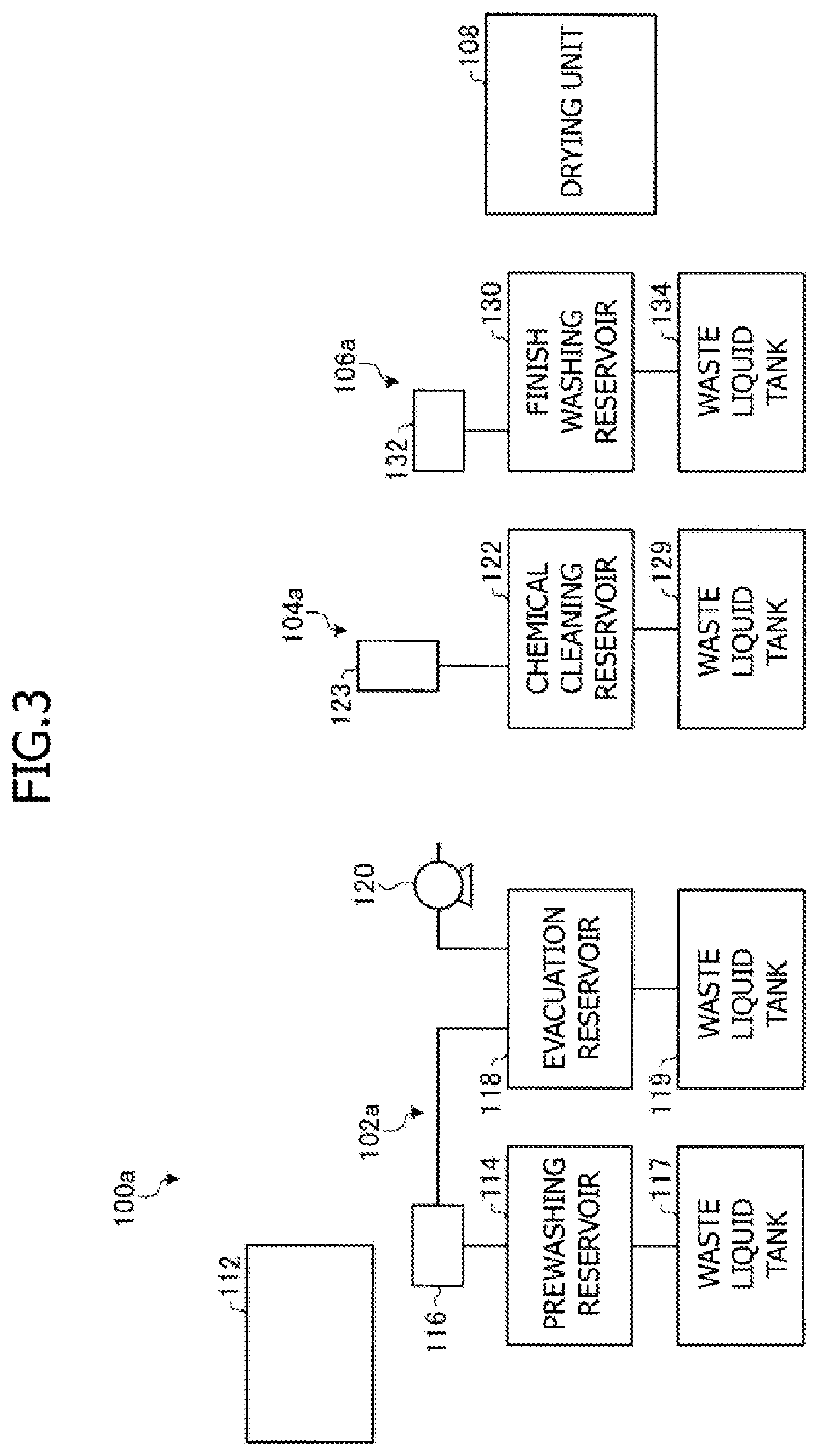
[0068]FIG. 3 shows a schematic configuration of a denitration catalyst regeneration system of a second embodiment. A denitration catalyst regeneration system 100a of the second embodiment shown in FIG. 3 can be combined with the denitration catalyst regeneration system 100 or with other embodiments. This is the case with other embodiments. Each of the embodiments is an example and can be partially combined with other embodiments.
[0069]As shown in FIG. 3, the denitration catalyst regeneration system 100a includes a prewashing unit 102a, a liquid agent cleaning unit 104a, a finish washing unit 106a, a drying unit 108, and a catalyst transporting apparatus 112. The catalyst transporting apparatus 112 is an apparatus which detaches the denitration catalyst from the denitration equipment provided with the denitration catalyst and transports the detached denitration catalyst. The 6 catalyst transporting apparatus 112 can include a crane for tran...
examples
[0086]Hereinafter, the present invention is described in further detail by use of Examples. The denitration catalyst regeneration method, the denitration catalyst regeneration system, and a cleaning agent for a denitration catalyst according to the present invention are not limited to Examples, to be described later.
1. Consideration I of Liquid Agent
[0087]First, the denitration catalyst regeneration method was carried out using several liquid agents with different inorganic acids and fluorine compounds mixed. For each of the liquid agents used, measurement was carried out for the restoration rate for the catalytic performance of the denitration catalyst (catalytic performance after regeneration processing / unused catalyst performance: K / K0), the silica concentration on the surface of the denitration catalyst (% by mass), and the calcium concentration on the surface of the denitration catalyst (% by mass). The reaction rate constant of the catalyst was used as an index of the catalyti...
PUM
| Property | Measurement | Unit |
|---|---|---|
| temperature | aaaaa | aaaaa |
| pH | aaaaa | aaaaa |
| pH | aaaaa | aaaaa |
Abstract
Description
Claims
Application Information
 - R&D
- Intellectual Property
- Life Sciences
- Materials
- Tech Scout
- Unparalleled Data Quality
- Higher Quality Content
- 60% Fewer Hallucinations
Browse by: Latest US Patents, China's latest patents, Technical Efficacy Thesaurus, Application Domain, Technology Topic, Popular Technical Reports.
© 2025 PatSnap. All rights reserved.Legal|Privacy policy|Modern Slavery Act Transparency Statement|Sitemap|About US| Contact US: help@patsnap.com


