Scroll type micro-compressor, and method for machining fixed scroll plate and orbit scroll plate thereof

a micro-compressor and scroll plate technology, applied in the field of scroll plate micro-compressors, can solve the problems of high precision, limited reports on the design and implementation method of such scroll plate compressors based on micro-machining techniques, and the inability of scroll type compressors to come into practice, so as to reduce the load mass of an electrostatically driven orbit scroll plate, prevent a top leakage, and improve the shape design of the pores

Active Publication Date: 2021-08-03
BEIJING UNIV OF CHEM TECH
View PDF8 Cites 0 Cited by
  • Summary
  • Abstract
  • Description
  • Claims
  • Application Information

AI Technical Summary

Benefits of technology

[0006]The present disclosure discloses a scroll type micro-compressor integrated on a monocrystalline silicon substrate, which introduces an Oldham ring structure in the scroll type micro-compressor for the first time, and reduces a load mass of an electrostatically driven orbit scroll plate by optimizing a shape of an orbit scroll plate substrate. As to the problems of the non-uniform electrostatically driving electric field and the voltage loss, the present disclosure improves the shape design of the pores, and proposes to change hydrophilia of inner surfaces to prevent a top leakage and facilitate capillary filling of a compression chamber. In terms of implementation, the present disclosure contains a detailed technological process for a scroll micro-compressor based on a monocrystalline silicon substrate.
[0009]In an embodiment of the present disclosure, a scroll type micro-compressor based on a monocrystalline silicon substrate comprises an orbit scroll plate and a fixed scroll plate each machined using a monocrystalline silicon substrate; a lower surface of a square substrate of the fixed scroll plate is provided with micropores featuring a high depth-to-width ratio for filling of an electrostatically driven electrode, and an upper surface of the substrate of the fixed scroll plate is integrally provided with a raised fixed scroll wall; a plurality of micropores uniformly distributed along the fixed scroll wall are provided to extend from the lower surface of the fixed scroll plate substrate into the fixed scroll wall through the fixed scroll plate substrate, for filling of an electrostatically driven electrode; a cross-sectional shape of the micropore is a fan ring, and inner and outer arc edges of the fan ring are each equidistant from corresponding edge of the fixed scroll wall, i.e., points on the inner arc edge of the fan ring are equidistant from an inside edge of the fixed scroll wall, and points on the outer arc edge of the fan ring are equidistant from an outside edge of the fixed scroll wall; the fan ring-shaped micropores are extended from the fixed scroll plate substrate into the fixed scroll wall, filled with an electrode material, and connected to the pads by wires; a through-hole is provided on the fixed scroll plate substrate and at a center of the fixed scroll wall as a discharge port; an annular shell is provided on the upper surface of the fixed scroll plate substrate and located outside the fixed scroll wall, and a side of the annular shell is provided with an inlet; an upper end face of the annular shell is provided with a pair of cylindrical keyways radially and symmetrically distributed with respect to the fixed scroll wall; an upper surface of a circular planar orbit scroll plate substrate is integrally provided with a raised orbit scroll wall; a pair of short arms are provided to radially extend from two ends of a diameter of the circular planar orbit scroll plate substrate, and either of the two short arms is provided with a raised cylindrical insertion key; a distance between centers of the two insertion keys is equal to a distance between centers of the two cylindrical keyways, and the insertion key is inserted into a corresponding keyway; a diameter of the insertion key is smaller than a diameter of the keyway; the insertion key and the keyway form an Oldham ring structure to prevent an autogiration of the orbit scroll plate; and the shape of the orbit scroll plate substrate is optimized to reduce the mass of the orbit scroll plate, including a minimized circular body portion connected to a pair of radially symmetric coplanar short arms for accommodating the Oldham ring insertion key, thereby reducing the mass of the load under electrostatic driving.
[0010]In an embodiment of the present disclosure, the orbit scroll plate and the fixed scroll plate may be subjected to surface treatments, so that sidewall surfaces of the scroll walls and upper surfaces of the substrates of the orbit scroll plate and the fixed scroll plate are hydrophilic, while top surfaces of the scroll walls are hydrophobic. The Chinese patent document with a Chinese patent number of CN200810177003.7 discloses an operating mechanism of the electrostatic driven micro scroll compressor, and the micro scroll compressor has its structures integrated within monocrystalline silicon. The compression efficiency of the compressor is affected by both the top leakage and the side leakage, while in the two leakage mechanisms, the top leakage affects the compressor efficiency more seriously. The capillary action of the liquid becomes significant in the minute structure, and during operation of the compressor, a top leakage risk will be caused by any tiny gaps due to that the top surface of the orbit scroll wall / the upper surface of the fixed scroll plate substrate and the top surface of the fixed scroll wall / the upper surface of the orbit scroll plate substrate are not completely sealed, so the compressed liquid can easily enter the tiny gaps under the capillary action. The hydrophobic treatment of the top surface of the scroll wall is favorable for limiting the top leakage caused under the capillary action, while the hydrophilicity of the inner wall of the compression chamber (the side surface of the scroll wall and the upper surface of the substrate) is favorable for restricting the liquid in the compression chamber, thereby improving the compression efficiency. In addition, the hydrophilicity of the inner wall of the compression chamber is favorable for the filling and the inner wall modification of the compression chamber by the capillary action. The method for the hydrophilic surface treatment includes, but not limited to, the silica deposition; and the hydrophobic surface treatment includes, but not limited to, grinding polished silicon, applying hydrophobic polymer coating, and the like.
[0014]The micropore of the present disclosure adopts a cross-sectional shape design of a fan ring, wherein inner and outer arc edges of the fan ring are each equidistant from corresponding edge of the fixed scroll wall, i.e., points on the inner arc edge of the fan ring are equidistant from an inside edge of the fixed scroll wall, and points on the outer arc edge of the fan ring are equidistant from an outside edge of the fixed scroll wall. As the prior arts adopt a cylindrical electrode, correspondingly, the prior arts adopt circularly cross-sectional micropores. But the distance between the boundary of the circular cross-section and the edge of the fixed scroll wall is extremely non-uniform, resulting in an non-uniform electrostatic field and a great field loss on the fixed scroll wall. When the present disclosure adopts the micropore having a cross-sectional shape of a fan ring, it is favorable to maintain a constant distance between the arc edge and the edge of the fixed scroll wall, which is equal to the technologically allowable minimum distance between the micropore boundary and the edge of the fixed scroll wall, thereby reducing a loss of the electric field, and maintaining uniformity of the electric field.
[0015]The present disclosure adopts the micropore having a cross-sectional shape of a fan ring, and when the etching reaches a certain depth, the micropore having a cross-sectional shape of a fan ring in the present disclosure has a larger effective area to receive the etching ion beam for a silicon deep reactive ion etching (DRIE), than the circularly cross-sectional micropore of the same radial size in the prior art, thereby reducing the difficulty in deep etching of the micropore with a high depth-to-width ratio.

Problems solved by technology

However, since the machining of the components of the scroll type compressor requires an extremely-high precision (a few micrometers) machining technique, the scroll type compressor did not come into practice until the application of the computer numeric control (CNC) technique in early 1970s.
Currently, there are very limited reports on the design and implementation method of such scroll type compressor based on the micromachining technique.
The California Jet Propulsion Laboratory of the National Aeronautics and Space Administration and the University of Southern California have collaborated on a method for machining a high depth-to-width ratio scroll wall using a LIGA technology, but the disadvantage of this method lies in a high cost of X-ray LIGA.
But the structure is not designed with any structure to prevent the autogiration of the orbit scroll plate, the adopted electrostatically driven electrode is a cylindrical structure, the electric field uniformity is poor and the driving voltage loss is large; in addition, the compression efficiency of the compressor is affected by both the top leakage and the side leakage, while in the two leakage mechanisms, the top leakage affects the compressor efficiency more seriously.
The capillary action of the liquid becomes significant in the minute structure, and during operation of the compressor, a top leakage risk will be caused by tiny gaps existing under conditions when the top of the orbit scroll wall / the upper surface of the fixed scroll plate substrate and the top surface of the fixed scroll wall / the upper surface of the orbit scroll plate substrate are not completely sealed, so the compressed liquid can easily enter the tiny gaps under the capillary action.
Besides, the machining technology uses the SOI substrate which is expensive.

Method used


Image

  • Scroll type micro-compressor, and method for machining fixed scroll plate and orbit scroll plate thereof
  • Scroll type micro-compressor, and method for machining fixed scroll plate and orbit scroll plate thereof
  • Scroll type micro-compressor, and method for machining fixed scroll plate and orbit scroll plate thereof

Examples


Embodiment Construction

[0049]The technical solutions in the embodiments of the present disclosure will be described clearly and completely as follows with reference to the drawings in the embodiments of the present disclosure. Obviously, those described are merely parts, rather than all, of the embodiments of the present disclosure. Based on the embodiments of the present disclosure, any other embodiment obtained by those skilled in the art without paying any creative labor should fall within the protection scope of the present disclosure.

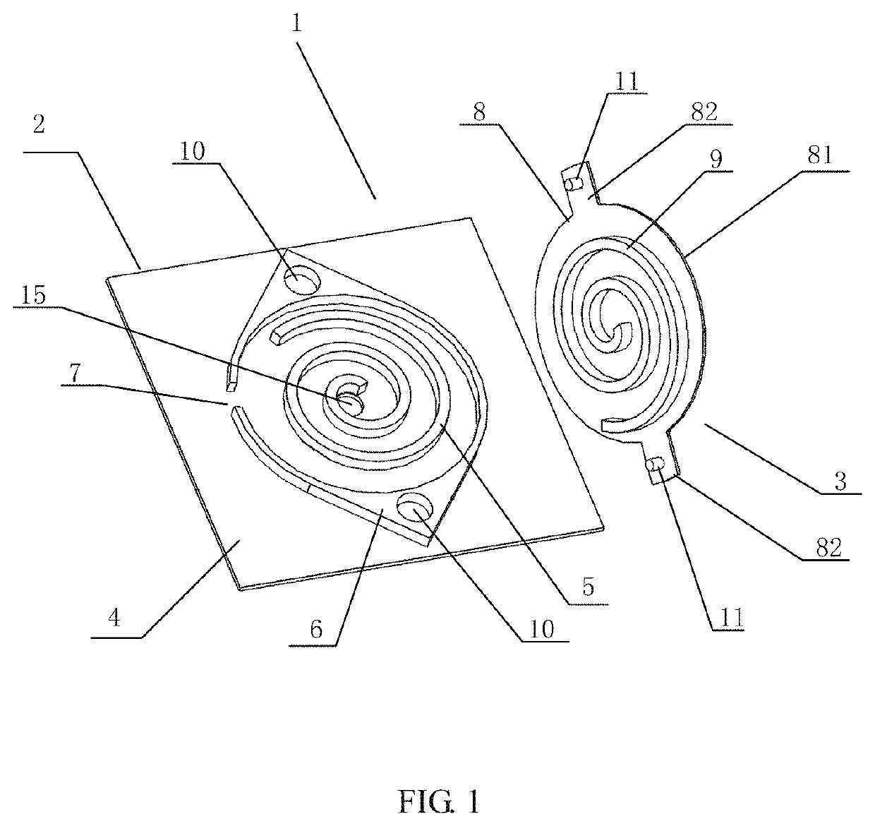
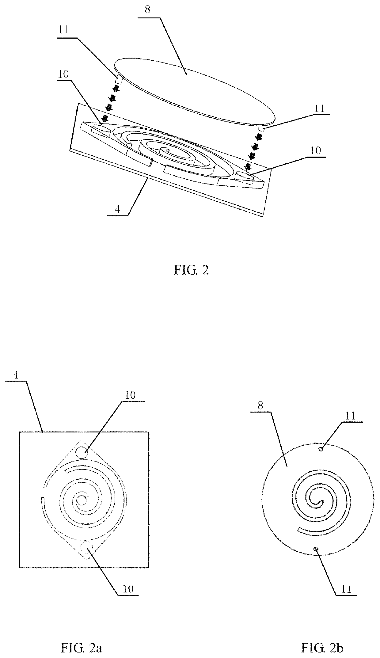
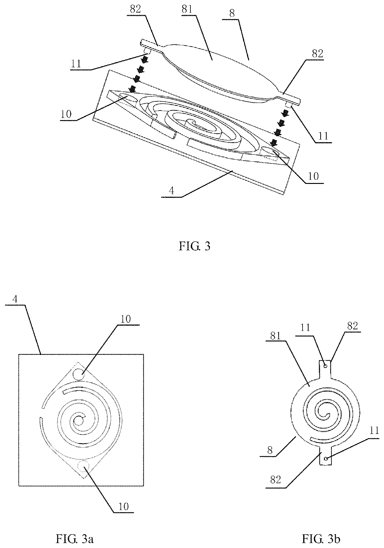
[0050]As shown in FIGS. 1, 4 and 5, the present disclosure proposes a scroll type micro-compressor 1 which is based on a monocrystalline silicon substrate and electrostatically driven, comprising a fixed scroll plate 2 and an orbit scroll plate 3 each integrally made with a monocrystalline silicon substrate to reduce the cost. As shown in FIG. 1, the fixed scroll plate 2 comprises: a fixed scroll plate substrate 4, a fixed scroll wall 5 and an annular shell 6 located out...


PUM

PropertyMeasurementUnit
depthaaaaaaaaaa
diameteraaaaaaaaaa
depthaaaaaaaaaa

Abstract

The embodiments of the present disclosure disclose a scroll type micro-compressor, and a method for machining a fixed scroll plate and an orbit scroll plate thereof. The scroll type micro-compressor comprises a fixed scroll plate and an orbit scroll plate each integrally made with a monocrystalline silicon substrate; the compressor device has an Oldham ring structure, and reduces a mass of the orbit scroll plate by optimizing a design of a substrate of the orbit scroll plate; a cross-sectional shape of a plurality of micropores provided on a lower surface of the fixed scroll plate is set as of a fan ring, in which an electrode material is accommodated to maintain an electric field uniformity and reduce an electric field loss; and hydrophilia of inner surfaces is changed to prevent a top leakage and facilitate capillary filling of a compression chamber.

Description

CROSS-REFERENCE TO RELATED APPLICATIONS[0001]This application claims priority to Chinese Patent Application No. 201811323370.3, filed on Nov. 8, 2018 and Chinese Patent Application No. 201811323362.9, filed on Nov. 8, 2018, both of which are hereby incorporated by reference in its entirety.TECHNICAL FIELD[0002]The present disclosure belongs to the technical field of compressors, and particularly relates to a scroll type micro-compressor and a method for machining a fixed scroll plate and an orbit scroll plate thereof.BACKGROUND ART[0003]A scroll type compressor comprises a pair of intermeshed, spiral-shaped scroll components, and compresses gases or liquid by causing an eccentric gyratory translation of a uniquely movable component, i.e., an orbit scroll, with respect to a fixed scroll which is held stationary. Such a concise design with less movable components makes the scroll type compressor be favorable over other compressors, such as a rotary-screw compressor or a reciprocating ...

Claims


Application Information

Patent Timeline
Patent Type & Authority Patents(United States)
IPC IPC(8): F04C18/02B81C1/00
CPCF04C18/0215B81C1/00087F04C18/0253F04C18/0269F04C18/0292F04C2230/10F01C17/066F05C2203/06
Inventor YU, DULIXING, XIAOXINGZHANG, CHAOMIN
Owner BEIJING UNIV OF CHEM TECH
Why Eureka
Try Eureka