Balloon dilator

a balloon dilator and balloon technology, applied in the field of balloon dilators, can solve the problems of multiple attempts and significant blood loss, difficulty in removing balloon dilators, and hemodynamic instability of patients, and achieve the effects of increasing the rigidity of the combined balloon dilator, quick removal, and improving the ease of insertion

Active Publication Date: 2021-11-02
HOGANSON DAVID M
View PDF12 Cites 1 Cited by
  • Summary
  • Abstract
  • Description
  • Claims
  • Application Information

AI Technical Summary

Benefits of technology

The technology described in this patent provides a dilator system for arterial and venous cannulas that has a smooth transition between the dilator and the cannula. This reduces the risk of complications during insertion and improves ease of use. The system includes a balloon dilator that can be securely positioned within the cannula and a stiffening element to increase rigidity. It also has an improved curve and a gel-filled balloon dilator that can be easily removed without deflation. Overall, this technology improves the insertion of cannulas and minimizes complications during medical procedures.

Problems solved by technology

The limitation of this system is that many of the cannulas, especially those used for the venous system, are simply cut tubes that are forced into the blood vessels through an open incision and to a pressurized vessel.
This is often done with some difficulty, including multiple attempts and significant blood loss.
On occasion, difficulty with cannulation during heart surgery or initiation of ECMO support results in hemodynamic instability of the patient, or even injury to the vessels being cannulated.
However, these dilators are often not well-secured to the cannulas, and can push back into the cannula during insertion and, importantly, there is still a step transition between the greatest diameter of the dilator and the greatest diameter of the cannula, which still can make these cannulas difficult to insert into the patient, particularly a small child with rather elastic vessels.
One particular cannula design that is most difficult to insert is the right angle-style cannulas used generally for superior vena cava and inferior vena cava cannulation, and occasionally for right atrial cannulation.
These cannulas have no dilators and can be difficult to easily position into a vein, either deep within the chest of a large patient or in the small and delicate veins of a young child.

Method used


Image

  • Balloon dilator
  • Balloon dilator
  • Balloon dilator

Examples


Embodiment Construction

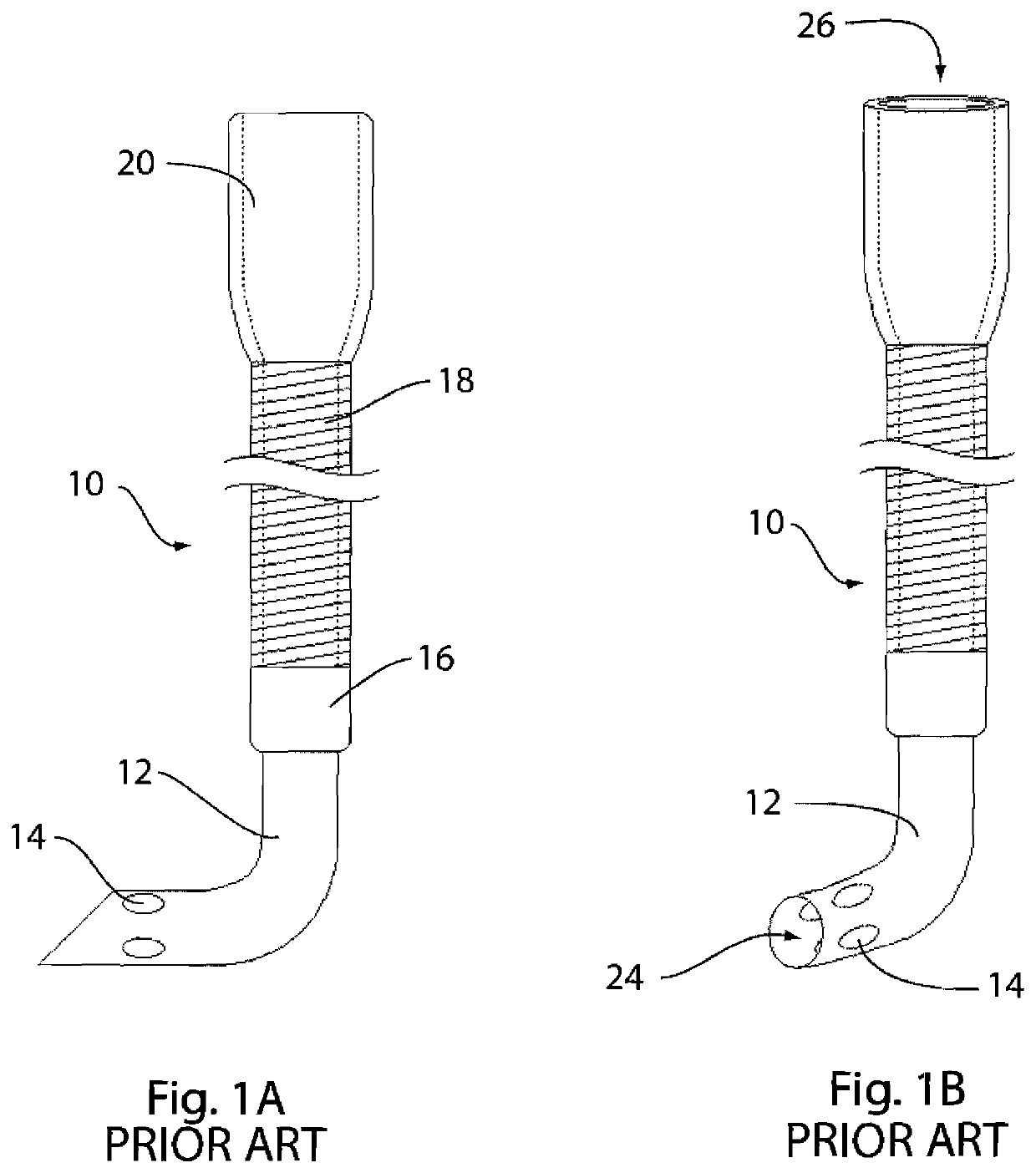
[0030]The present invention overcomes many of the prior art challenges associated with dilators for arterial and venous cannulas. The advantages and other features of the technology disclosed herein will become more readily apparent to those having ordinarily skill in the art, and the following detailed description of certain embodiments taken into conjunction with the drawing which set forth representative embodiments of the present invention and wherein like reference numerals identify similar structural elements.

[0031]It is to be understood that the subject technology is not intended to be limited to the particular constructs and methods described in the described embodiments, as one skilled in the art can extend the concepts involved using variations which are obvious after reading the present disclosure. Although any methods and materials, similar or equivalent to those described herein, may be useful in a practice of the subject technology, certain compositions, films, methods...


PUM


Abstract

A dilator system for arterial and venous cannulas, where there is a smooth transition between the dilator and the outer wall of the cannula. One aspect of the subject technology provides a blunt-tip cannula that is used as a dilator for insertion of an arterial or venous cannula. The balloon might either be a single diameter or may have a larger diameter at the distal portion such that the diameter of the distal portion of the balloon dilator matches the diameter of the cannula at the tip. Another aspect of the subject technology is a balloon dilator for cannulae that may be positioned over a guidewire, for guidewire-directed placement of a cannula within a vessel, duct, lumen or heart structure of the body. Another aspect of the subject technology is an inflation system for the balloon dilator, such that the balloon dilator may be deflated and quickly removed from the cannula after the cannula has been positioned and secured within the vessel, duct, lumen or heart structure. Another aspect of the subject technology includes a stiffening element in the balloon dilator along its shaft to increase the rigidity of the combined balloon dilator and cannula to provide improved ease of insertion. Another aspect of the subject technology is an improved curvature of the shape of the right angle dilator that achieves more uniform flow within the dilator and ease of insertion and more even flow within the cannula, and ease of insertion of and retraction of the balloon dilator. Another aspect of the subject technology is a gel-filled balloon dilator that improves ease of insertion of the cannula within the vessel, duct, lumen or heart structure, and can be removed without deflation.

Description

CROSS-REFERENCE TO RELATED APPLICATION(S)[0001]This patent document claims the benefit of U.S. Provisional Application No. 62 / 113,243, filed on Feb. 6, 2015 in the name of David M. Hoganson. The entire contents of this commonly owned patent application are expressly incorporated by reference herein.STATEMENT REGARDING FEDERALLY SPONSORED RESEARCH[0002]None.BACKGROUND OF THE INVENTION[0003]Heart surgery and extracorporeal membrane oxygenation (ECMO) are made possible by connecting a patient to a mechanical circulatory support system. The cardiopulmonary bypass circuit, or ECMO circuit, consists of a pump and an oxygenator, which provide the function of the heart and the lungs to support patients during surgery or temporarily during critical illness. Connecting patients to these mechanical circulatory support systems involves placement of cannulas in arterial and venous systems (or just in the venous system) of the patient to drain blood from the patient to the support circuit, and th...

Claims


Application Information

Patent Timeline
IPC IPC(8): A61M25/10A61M25/09A61M1/36A61B17/34
CPCA61M25/10A61B17/3439A61B17/3494A61M1/3659A61M25/09A61M25/1025A61M25/10182A61B17/3496A61M29/02A61M25/0041
Inventor HOGANSON, DAVID M.
Owner HOGANSON DAVID M
Why Eureka
Try Eureka