
Apparatus, system and method for the detection and quantification of conductance of right-to-left cardiac shunts

a technology conductance measurement, applied in the field of apparatus, system and method for the detection and quantification of conductance of right-to-left cardiac shunt, can solve the problems of invalid shunt test and need to be repeated, so as to minimize the possibility of cerebrovascular accidents, reduce the frequency and severity of migraines, and reduce the occurrence of primary

Active Publication Date: 2022-03-22
PFOMETRIX LLC
View PDF10 Cites 2 Cited by
  • Summary
  • Abstract
  • Description
  • Claims
  • Application Information

AI Technical Summary

Benefits of technology

This patent describes an apparatus, system, and method for controlling the release of a substance called contrast agent into the heart during a medical test. The system detects the arrival of the agent using a special transducer and a computer algorithm, and then uses a solenoid to create a partial vacuum to quickly open the airways. The system accurately measures the time it takes for the contrast agent to transit from the injection point to the heart, which is used to detect and measure the conductance of a shunt in the heart. The technical effect of this patent is to provide a reliable and accurate method for releasing the contrast agent at the right time and in the right amount, which can improve the accuracy of medical tests and procedures.

Problems solved by technology

If the exhalation pressure level and duration does not meet the predetermined minimum criteria (e.g., minimum exhalation pressure minimum and duration of exerted exhalation pressure), then the operator is advised that the shunt test just completed is invalid and needs to be repeated due to an inadequate Valsalva maneuver.

Method used


Image

  • Apparatus, system and method for the detection and quantification of conductance of right-to-left cardiac shunts
  • Apparatus, system and method for the detection and quantification of conductance of right-to-left cardiac shunts
  • Apparatus, system and method for the detection and quantification of conductance of right-to-left cardiac shunts

Examples


Embodiment Construction

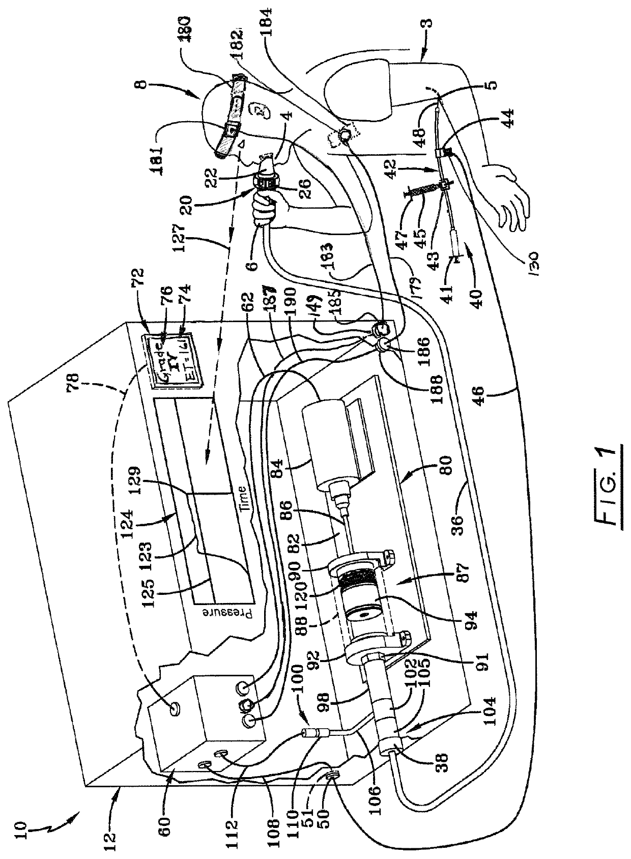
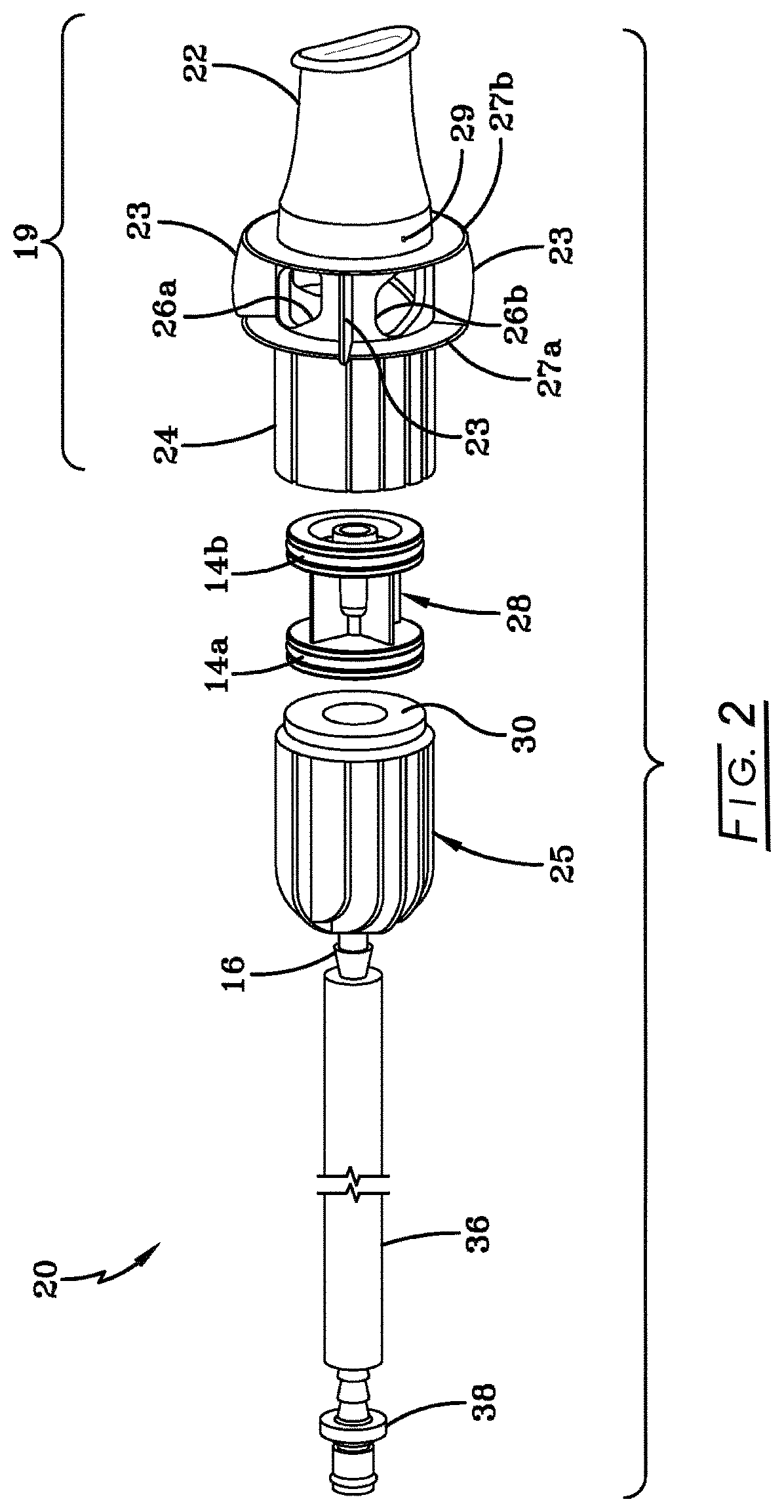
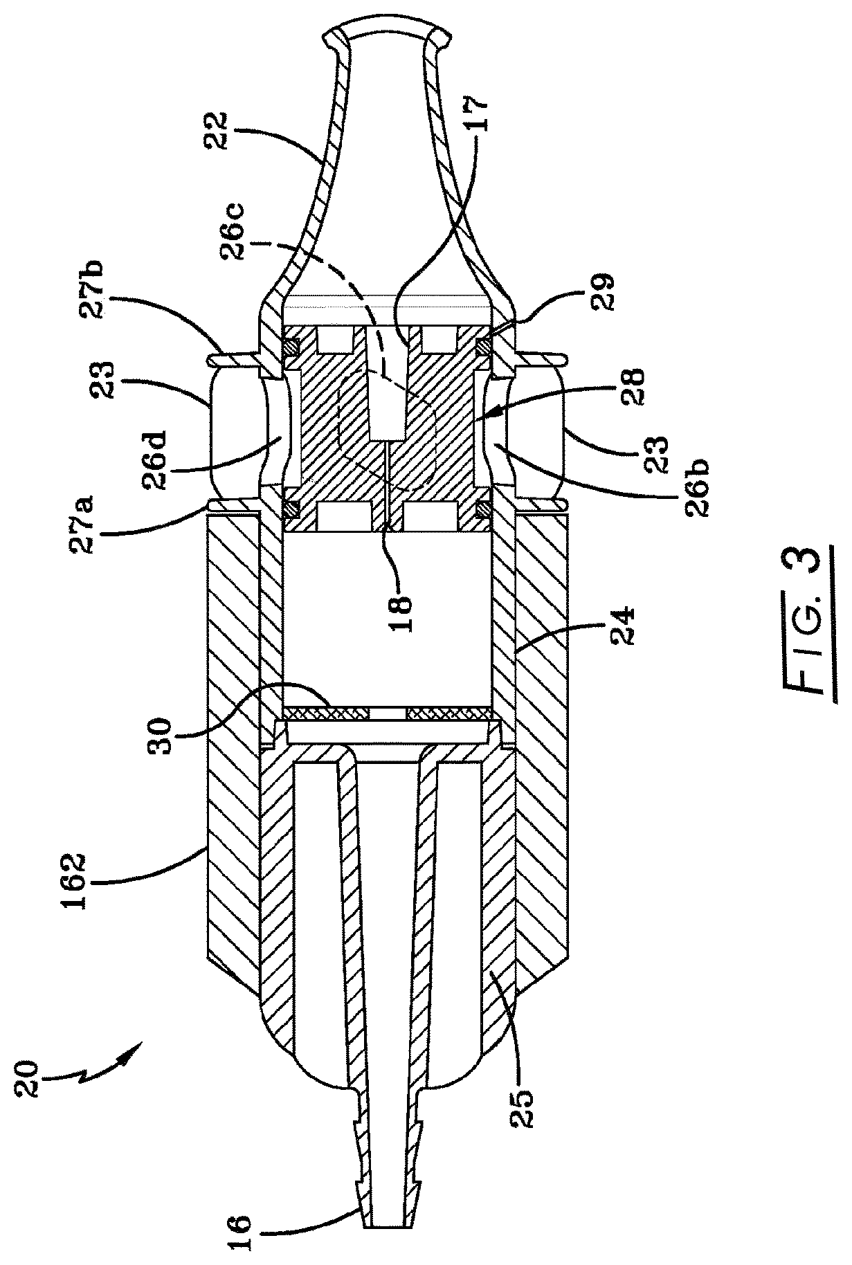
[0088]Referring to FIG. 1, an illustrative embodiment of the present disclosure is described showing the principal components of a system for detecting and quantifying the conductance of a right-to-left shunt using a Transcranial Doppler ultrasound method. The principal components include [a] headband 180 incorporating a first set of Doppler ultrasound transducer arrays 181 for insonation of targeted intracranial arteries (e.g., middle cerebral arteries) in one or both hemispheres of the skull of subject 8, [b] a second Doppler ultrasound transducer 182 positioned on the surface of the precordium of subject 8 to detect the arrival of contrast agent in the right atrium (not shown), [c] catheter set 40 including venous access needle accessing antecubital vein, two syringes 41 and 47 for combining and agitating a mixture of saline, air and the subject's blood as well as a microbubble counting cell 44 and removably attachable digital image sensor (not shown), [d] mouthpiece assembly 20 ...


PUM


Abstract

A system for detecting / quantifying the conductance of a right-to-left cardiac shunt includes a mouthpiece assembly, a solenoid-driven vacuum / pressurization assembly; a controller for operating the solenoid-driven vacuum / pressurization assembly; and a monitor for displaying the instructions from the controller. A microbubble counting cell and digital image sensor are combined with software-based image analysis to determine a number of microbubbles contained in a microbubble counting zone. A monitor enables operator specification of total volume of contrast agent to be injected into the patient. One or more first Doppler ultrasound transducer arrays are positioned adjacent to targeted intracranial arteries at one side of the skull or a pair of first Doppler ultrasound transducer arrays positioned adjacent to targeted intracranial arteries at both sides of the skull. A second Doppler ultrasound transducer is positioned on the precordium of the patient to detect the arrival of microbubble-containing contrast agent in the right atrium of the patient.

Description

CROSS-REFERENCE TO RELATED APPLICATIONS[0001]This application claims benefit of provisional application 62 / 513,460 filed Jun. 1, 2017.STATEMENT REGARDING FEDERALLY SPONSORED RESEARCH[0002]Not applicable.BACKGROUND[0003]Cryptogenic strokes and transient ischemic attacks (“TIAs”) are those in which no obvious cause is found by patient history, carotid Doppler studies, or cardiac conditions such as atrial fibrillation, myocardial infarction, or valve diseases. Patent foramen ovale (“PFO”), which is a small flap-valve hole in the heart, has been associated with cryptogenic stroke allowing paradoxical embolism from the veins to the brain through a right-to-left shunt (“RLS”). Normally, blood returning to the heart from the veins is re-oxygenated when it is pumped from the right side of the heart and then through the lungs. However, in people with PFO, the venous blood, which may contain clots, may instead travel through the hole (i.e., the PFO) between the upper chambers of the heart and...

Claims


Application Information

Patent Timeline
IPC IPC(8): A61B8/08A61B5/02G06T7/00A61B5/026A61B8/00A61B5/087A61B8/06A61B5/00A61M25/10
CPCA61B8/481A61B5/026A61B5/02028A61B8/44A61B8/4416A61B8/4477A61B8/4494A61B8/46A61B8/461A61B8/467A61B8/488A61B8/52G06T7/0012A61B5/087A61B5/742A61B8/06A61M2025/102A61B5/08A61B8/0808A61B8/4227A61B8/5207
Inventor EGGERS, PHILIP E.EGGERS, ANDREW R.DOBSON, DAVID THOMAS
Owner PFOMETRIX LLC
Learn More