Magnetic shielding unit for wireless power transmission and wireless power transmission module including same

a technology of electromagnetic shielding unit and wireless power transmission, which is applied in the direction of inorganic material magnetism, magnetic/electric field screening, inductance, etc., can solve the problems of reducing the efficiency of transmission/reception, electromagnetic wave signals not only present between the transmitting module and the receiving module, and leaked to the surrounding

Active Publication Date: 2022-08-09
AMOTECH
View PDF21 Cites 0 Cited by
  • Summary
  • Abstract
  • Description
  • Claims
  • Application Information

AI Technical Summary

Benefits of technology

[0010]To solve the above problem and defects, it is an object of the present disclosure to provide a magnetic field shielding unit for wireless power transmission that can exhibits excellent magnetic characteristics in the operating frequency band for wireless power signal transmission to improve the wireless power transmission efficiency and extend the transmission distance of the wireless power signal.
[0011]It is another object of the present disclosure to provide a magnetic field shielding unit for wireless power transmission having a ferrite magnetic body which has characteristics of an excellent magnetic shielding, a high mechanical strength, a low temperature sintering and a prevention of twisting.
[0012]Furthermore, it is still another object of the present disclosure to provide the wireless power transmission module capable of significantly increasing the transmission / reception efficiency and extending transmission / reception distance of wireless power signal through the magnetic field shielding unit, even if various kinds of antennas having various structures, shapes, sizes and intrinsic characteristics (for example, inductance, resistivity, and the like) are integrated.

Problems solved by technology

Now, with the use of higher frequencies, the problem of performance degradation of antennas due to miniaturization has emerged.
The electromagnetic wave signals are not only present between the transmitting module and receiving module but also leaked to the surrounding.
Leaked electromagnetic wave may make problems such as a reduction of the transmission / reception efficiency, a shorten transmission / reception distances, and an adverse affectation for users using other components and devices disposed around the module.
However, since the known ferrite has a low magnetic permeability and a high loss magnetic permeability in a low operating frequency band for wireless power transmission, it is difficult to exhibit a magnetic shielding effect at a desired level when known ferrite is applied as a magnetic body for shielding a magnetic field in a frequency band ranging from several tens to several hundreds kHz, which is suitable for wireless power transmission.
In addition, the known ferrite has a problem of lowering the wireless power transmission efficiency and shortening the wireless power transmission distance.
Further, in the case of a shielding member using the known ferrite as a magnetic material, it is difficult to maintain a uniform plate shape such that the molded body is twisted due to low mechanical strength and high temperature sintering of the magnetic body itself.

Method used

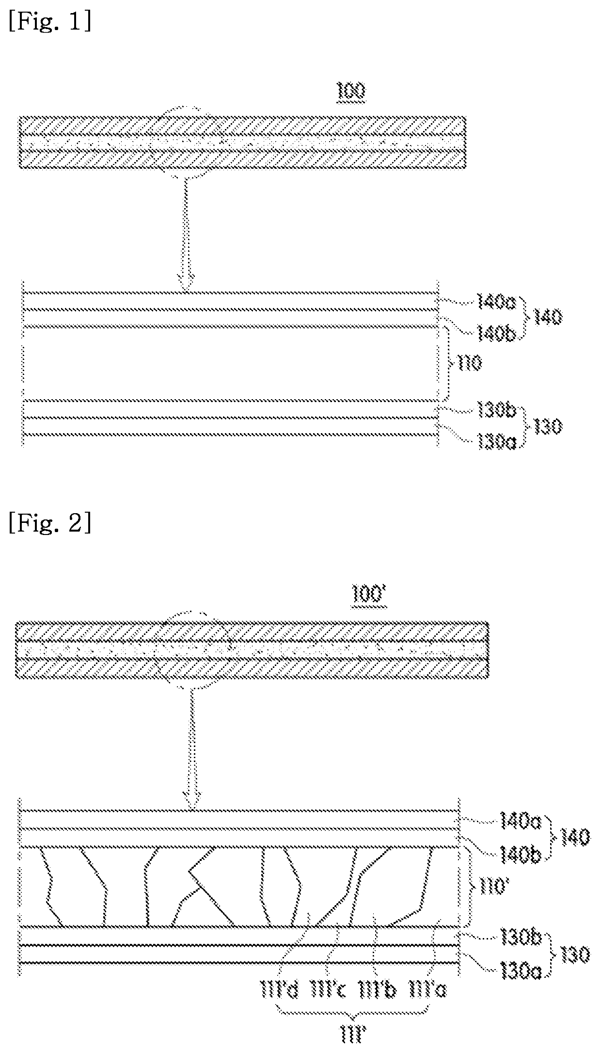

Image

  • Magnetic shielding unit for wireless power transmission and wireless power transmission module including same
  • Magnetic shielding unit for wireless power transmission and wireless power transmission module including same
  • Magnetic shielding unit for wireless power transmission and wireless power transmission module including same

Examples


preparation example 1

[0119]10 parts by weight of polyvinyl alcohol relative to 100 parts by weight of a ferrite powder having an average particle diameter of 0.75 μm (48.5 mol % of Fe2O3, 4.1 mol % of NiO, 28.8 mol % of ZnO, 10.3 mol % of CuO and 8.2 mol % of MgO) 50 parts by weight were mixed, dissolved and dispersed in a ball mill. Thereafter, the mixture was charged into a mold having cylindrical holes each having a diameter of 0.5 mm and a height of 0.5 mm and press-molded to produce granules. The granules thus prepared were molded into a mold having a final molding density of 3.2 g / cm3 with an outer diameter of 18 mm, an inner diameter of 13 mm, and a thickness of 3.7 mm, followed by degreasing at 500 for 10 hours and calcining at 940 for 2.2 hours and cooled to produce bulk ferrite.

preparation examples 2 to 14

[0120]The ferrite powder was prepared in the same manner as in Preparation Example 1 except that the composition / composition ratio of the ferrite powder was changed as shown in Table 1 to prepare bulk ferrite as shown in Table 1 below.

experimental example

[0122]The real and imaginary parts of the complex permeability were shown in Tables 1 to 2 by measuring the permeability at 100 kHz, 200 kHz and 13.56 MHz for the samples prepared according to the preparation examples and comparative preparation examples.

[0123]Specifically, the permeability was measured using an impedance analyzer (4294A Precision Impedance Analyzer and 42942A Terminal adapter kit). The test fixture was a 16454A magnetic body test fixture and measured at an Osc level of 500 mV.

[0124]

TABLE 1Prep.Prep.Prep.Prep.Prep.Prep.Prep.Prep.Prep.Prep.Ex. 1Ex. 2Ex. 3Ex. 4Ex. 5Ex. 6Ex. 7Ex. 8Ex. 9Ex. 10CompositionFe2O348.548.549.349.348.548.549.349.349.349.3of FerriteNiO4.14.64.62.53.13.65.66.67.67.1ZnO28.828.327.927.929.929.327.927.927.925.4CuO10.310.310.111.210.310.310.110.110.110.1MgO8.28.28.19.18.28.27.16.15.18.1Total100100100100100100100100100100ZnO(Mol %) / 7.026.156.0611.169.658.144.984.233.673.58NiO(Mol %)Density of Ferrite(g / cm3)5.085.095.065.15.075.095.085.15.155.08Permea...


PUM

PropertyMeasurementUnit
frequencyaaaaaaaaaa
thicknessaaaaaaaaaa
frequencyaaaaaaaaaa

Abstract

Disclosed is a magnetic field shielding unit for wireless power transmission. The magnetic field shielding unit for wireless power transmission includes a magnetic shielding layer formed of ferrite fragments containing magnesium oxide (MgO) shredded to improve flexibility of the magnetic field shielding unit. The ferrite containing magnesium oxide has a real part (μ′) of the complex permeability of 650 or more at a frequency of 100 kHz. Accordingly, it is possible to prevent influence of a magnetic field on components of a mobile terminal device or a body of a user who uses the same, and to further increase the characteristics of the combined antennas even if the magnetic field shielding unit is combined with various kinds and purposes of antennas having various structures, shapes, sizes and intrinsic characteristics (inductance, resistivity, etc.).

Description

CROSS-REFERENCE TO RELATED APPLICATION[0001]This application is a U.S. National Stage of PCT / KR2016 / 013193 filed in the Korean language on Nov. 16, 2016, entitled: “MAGNETIC SHIELDING UNIT FOR WIRELESS POWER TRANSMISSION AND WIRELESS POWER TRANSMISSION MODULE INCLUDING SAME” which application claims priority to Korean Application No. 10-2015-0160592 filed on Nov. 16, 2015, which applications are each hereby incorporated herein by reference in their entireties.PARTIES TO A JOINT RESEARCH AGREEMENT[0002]The presently claimed invention was made by or on behalf of the below listed parties to a joint research agreement. The joint research agreement was in effect on or before the date the claimed invention was made, and the claimed invention was part of the joint research agreement and made as a result of activities undertaken within the scope of the join research agreement. The parties to the joint research agreement are AMOTECH CO., LTD. and AMOSENSE CO., LTD.BACKGROUND1. Technical Fiel...

Claims


Application Information

Patent Timeline
Patent Type & Authority Patents(United States)
IPC IPC(8): H05K9/00H02J50/12H02J50/70H01F27/36H01Q1/22H01Q1/52H01F1/37H01F27/255C04B35/03C04B35/26H01F38/14
CPCH05K9/0075C04B35/03C04B35/26H01F1/37H01F27/255H01F27/36H01F27/366H01F38/14H01Q1/2208H01Q1/526H02J50/12H02J50/70H01F41/0246C04B35/2608C04B2235/6025C04B2235/3206C04B2235/3279C04B2235/3281C04B2235/3284C04B35/64C04B35/638C04B2235/5445H01F10/20
Inventor LEE, WOONG YONGJANG, KIL JAEKIM, SEONG TAEKIM, SU JUNG
Owner AMOTECH
Why Eureka
Try Eureka