Combined fabricating method for gradient nanostructure in surface layer of metal workpiece

a technology of gradient nanostructure and surface layer, which is applied in the field of surface engineering technology and laser shock peening technology, can solve the problems of structural stability degradation, work hardening ability disappearance, and severe reduction of plasticity and toughness of nanostructured materials

Active Publication Date: 2022-09-20
JIANGSU UNIV
View PDF8 Cites 0 Cited by
  • Summary
  • Abstract
  • Description
  • Claims
  • Application Information

AI Technical Summary

Benefits of technology

[0017](1) The method provided in the present invention effectively realizes controlled and combined preparation of gradient nanostructure in the surface layer of a metal workpiece (aluminum alloy, titanium alloy, magnesium alloy, stainless steel, nickel-based superalloy, and magnesium alloy, etc.), and provides a novel and effective method for strengthening and reparation of key and important metal parts in the aeronautic and astronautic industry, automobile manufacturing and ship building industries, and chemical industry, etc.;
[0018](2) With the method provided in the present invention, gradient nanostructure in desirable layer thickness can be obtained in the surface layer of the metal workpiece material, and the micro-structural distribution of gradient nanostructure in the surface layer can be optimized, and a practical method is put forward innovatively on the basis of present technical feasibility against present technical limitations;
[0019](3) With the method provided in the present invention, the surface roughness of the metal workpiece material is effectively improved, the surface quality of the metal workpiece material is effectively improved, and the cost of post-treatment of the surface of the metal workpiece is effectively reduced;
[0020](4) The method provided in the present invention breaches the “reversed relationship” between material strength and plasticity of metal workpieces, ensures coexistence of good plasticity and high strength, and greatly improves overall mechanical properties of metal workpieces, including fatigue life and wear resistance, etc.

Problems solved by technology

As the strength and hardness are increased significantly, the plasticity and toughness of nanostructured materials are severely decreased, the work hardening ability disappears, and the structural stability is degraded.
Those drawbacks limit the application and development of nanostructured materials.
As high strength and lighter weight materials are now primarily used for engineering structures, conventional homogeneous materials, such as coarse crystalline materials and nanostructured materials, cannot meet the performance requirements for engineering structural parts in extreme service environments anymore.

Method used


Image

  • Combined fabricating method for gradient nanostructure in surface layer of metal workpiece
  • Combined fabricating method for gradient nanostructure in surface layer of metal workpiece

Examples


embodiment 1

[0027]An example of preparing gradient nanostructure in the surface layer of magnesium alloy with the method described above, including the following steps:

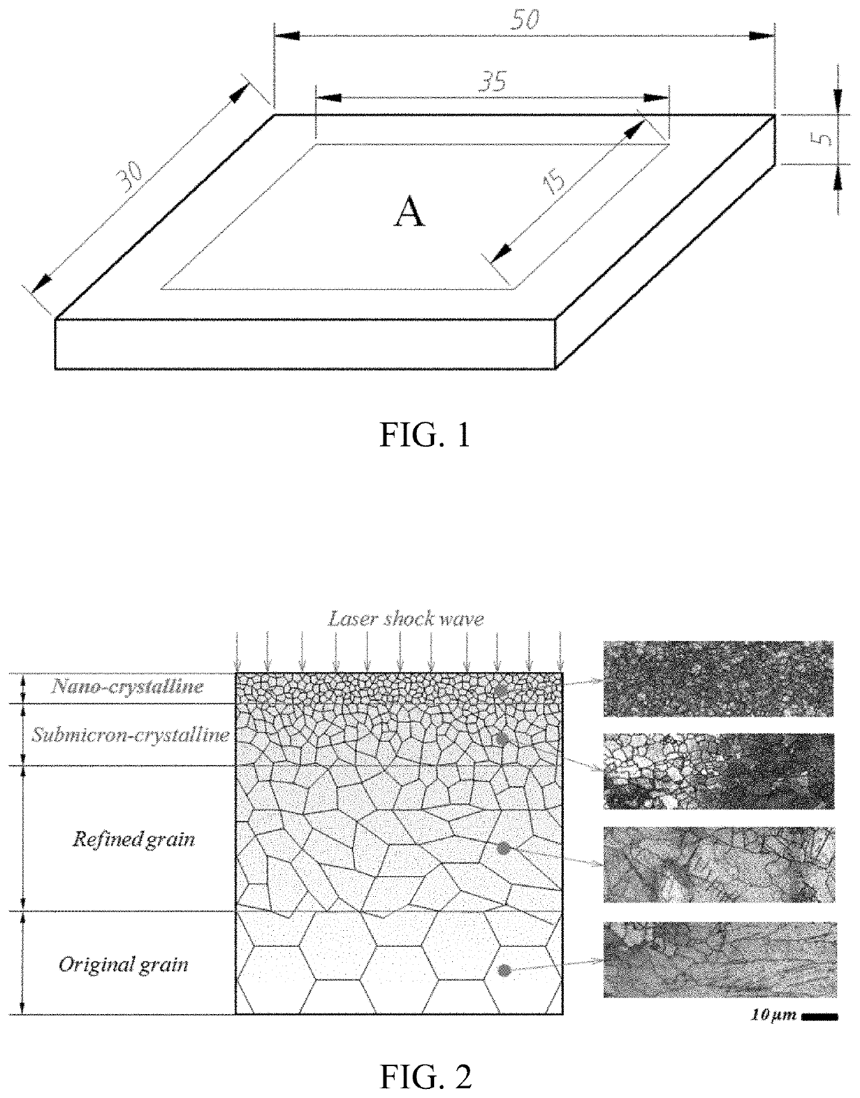
[0028](1) Two AM50 magnesium alloy samples in 30 mm×50 mm×5 mm dimensions are selected for comparison test, the two samples are denoted as sample 1 and sample 2 respectively, and the treated area A is shown in FIG. 1.

[0029](2) LSP treatment is carried out in the area A determined in the step (1) for the sample 1 and sample 2, wherein, the parameters of LSP are as follows: the spot is in a circular shape in 3 mm diameter, the pulse width is 10 ns, the pulse energy is 12 J, the overlap ratio in the transverse direction and longitudinal direction is 50%, and the number of coverage layers is 1.

[0030](3) The sample 2 is treated by SMAT, wherein, the parameters of SMAT are as follows: the vibration frequency of the system is 50 Hz, the ball diameter is 8 mm, and the treatment time is 30 min.

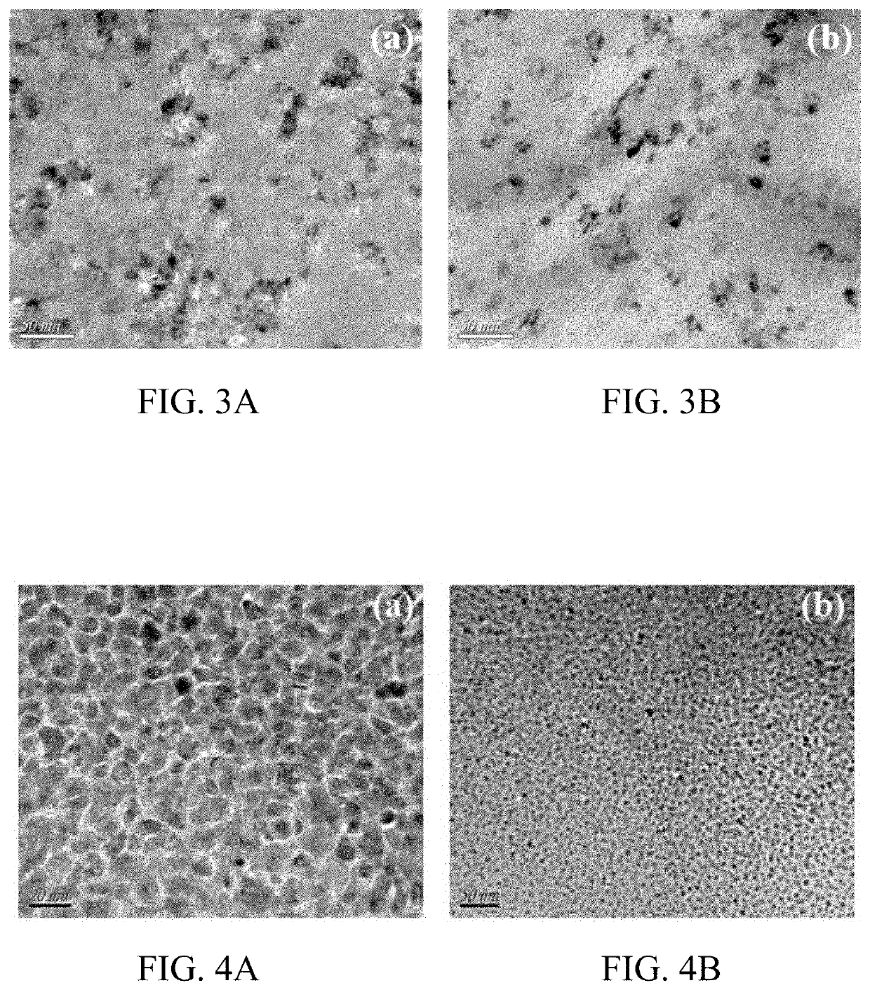
[0031]As shown in FIG. 3, wherein, FIG. 3(a) ...

embodiment 2

[0032]An example of preparing gradient nanostructure in the surface layer of copper alloy with the method described above, including the following steps:

[0033](1) Two H62 brass samples in 30 mm×50 mm×5 mm dimensions are selected for comparison test, the two samples are denoted as sample 1 and sample 2 respectively, and the treated area A is shown in FIG. 1.

[0034](2) LSP treatment is carried out in the area A determined in the step (1) for the sample 1 and sample 2, wherein, the parameters of LSP are as follows: the spot is in a circular shape in 3 mm diameter, the pulse width is 10 ns, the pulse energy is 6 J, the overlap ratio in the transverse direction and longitudinal direction is 50%, and the number of coverage layers is 1.

[0035](3) The sample 2 is treated by SMAT, wherein, the parameters of the surface mechanical attrition are as follows: the vibration frequency of the system is 50 Hz, the ball diameter is 8 mm, and the treatment time is 15 min.

[0036]As shown in FIG. 4, wherei...


PUM

PropertyMeasurementUnit
thicknessaaaaaaaaaa
thicknessaaaaaaaaaa
diameteraaaaaaaaaa

Abstract

Provided is a combined fabricating method for gradient nanostructure in the surface layer of a metal workpiece. A plastic deformation layer in great depth is induced by laser shock peening, then the surface of the metal workpiece is nanocrystallized by surface mechanical attrition treatment, and finally a gradient nanostructure is obtained in the surface layer of the metal workpiece with desirable layer thickness and optimized micro-structure distribution.

Description

CROSS REFERENCE TO RELATED APPLICATIONS[0001]This application is a National Stage Application of International Application Number PCT / CN2017 / 087532, filed Jun. 8, 2017; which claims priority to Chinese Application No. 201710273187.6, filed Apr. 25, 2017.TECHNICAL FIELD[0002]The present invention relates to the field of surface engineering technology and laser shock peening technology, in particular to a combined fabricating method for gradient nanostructure in the surface layer of a metal workpiece.BACKGROUND ART[0003]Nano-metal materials have advantages including high strength and hardness, good physical properties, high wear resistance, and good hot-workability, etc. Through nanocrystallization of the structure, the material strength and hardness can be increased by several times or even tens of times, without changing the chemical composition of the material. The report of Emerging Science and Technology Trends: 2016-2045 issued by the US Military in 2016 puts forward 24 emerging...

Claims


Application Information

Patent Timeline
Patent Type & Authority Patents(United States)
IPC IPC(8): C21D1/09B24C1/10C21D7/06C21D10/00B23K26/0622B23K26/06B23K26/073B82Y30/00
CPCC21D1/09B23K26/0622B23K26/0626B23K26/073B24C1/10C21D7/06C21D10/005B82Y30/00B82Y40/00
Inventor LU, JINZHONGWU, LIUJUNLUO, KAIYUJI, SHIJIE
Owner JIANGSU UNIV
Why Eureka
Try Eureka