Wiring method and wiring apparatus

a wiring apparatus and wiring method technology, applied in the direction of magnets, glue vessels, magnets, etc., can solve the problems of complex wiring apparatus construction, high cost, and high cost of wiring apparatus,

Inactive Publication Date: 2001-08-09
FURUKAWA ELECTRIC CO LTD
View PDF0 Cites 26 Cited by
  • Summary
  • Abstract
  • Description
  • Claims
  • Application Information

AI Technical Summary

Problems solved by technology

However, there are many problems that hinder manufacturing a planar coil of desired properties at low cost and with high yield.
This technique, however, needs an expensive ultrasonic vibration machine for heating the wire conductor just before it is laid on the substrate.
This makes a wiring apparatus complicated in construction and high in cost.
Further, controlling the wire temperature is very difficult.
If the wire temperature varies, a uniform adhesion of the wire conductor to the adhesive layer cannot be attained, causing an incorrect conductor pattern.
Further, even with such a large heating unit, it is difficult to heat the entirety of the patterned wire conductor uniformly at a time.
If the patterned wire conductor is not heated uniformly, the wire conductor cannot be uniformly embedded in the insulating sheet, and, for example, part of the wire conductor rises from the insulating sheet.
This may cause deformation and / or breakage of the patterned wire conductor.
However, this method requires a complicated process for making an antenna coil, and makes it difficult to form an antenna coil composed of coil parts or coil sections arranged at a sufficiently high density, because adjacent coil parts can be short-circuited if the spacing therebetween is small.
Thus, the antenna coil formed by etching is not satisfactory in respect of antenna characteristics and manufacturing cost.
With these techniques, however, it is generally difficult to provide an antenna coil with a thick conductor, posing problems in respect of the bending strength and tensile strength of the antenna coil, as well as the strength and reliability of the antenna coil mounted to an IC card.
However, these methods require severe control of hot air temperature and conductor heating temperature, respectively.
When ultrasonic vibration is used, an expensive ultrasonic vibrator is required, which causes an increased equipment cost and fatigue breakage of a wire conductor attributable to ultrasonic vibration.

Method used


Image

  • Wiring method and wiring apparatus
  • Wiring method and wiring apparatus
  • Wiring method and wiring apparatus

Examples


first embodiment

[0077] With reference to the drawings, a wiring apparatus according to the present invention will be described below.

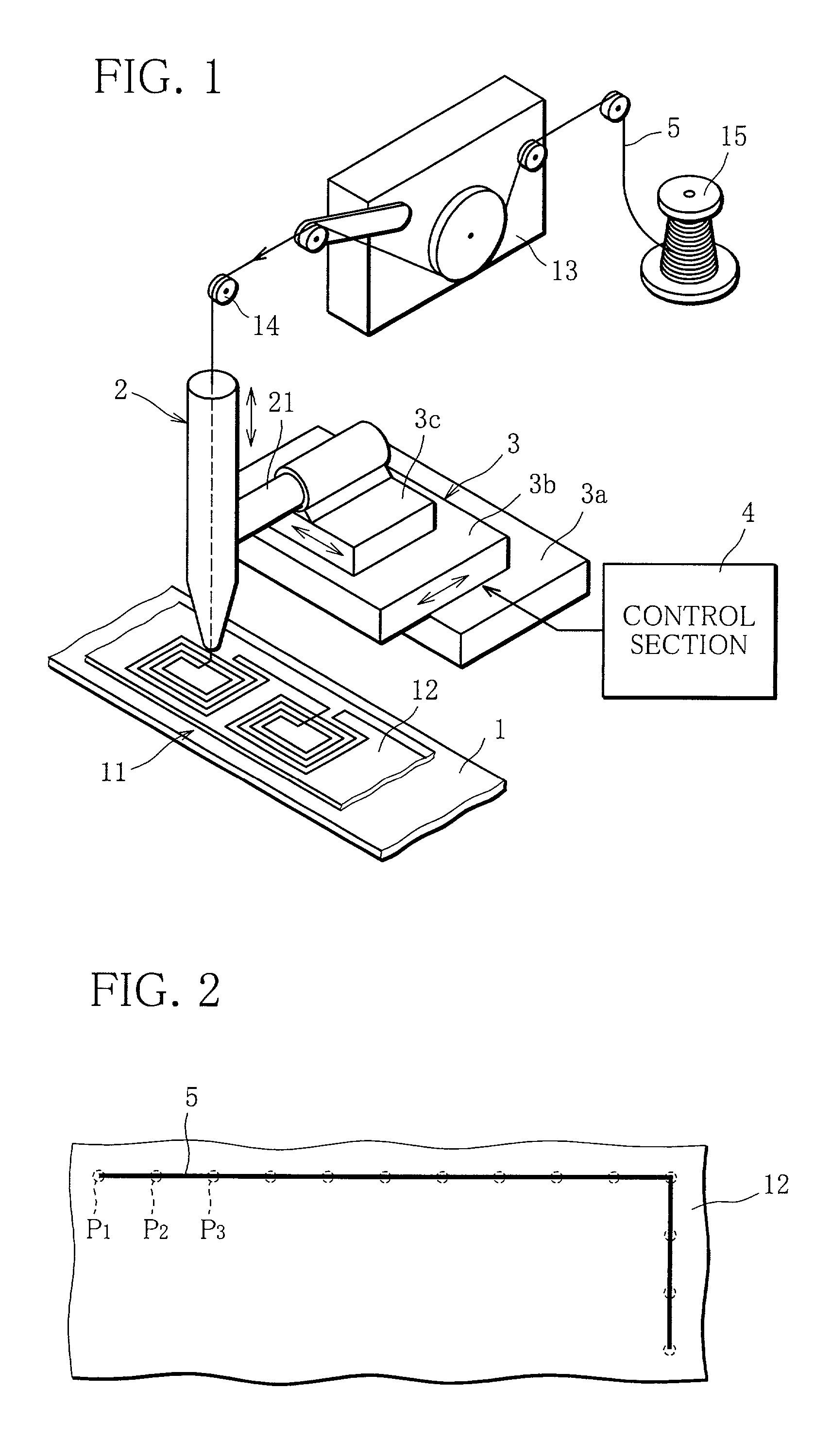
[0078] In FIG. 1, the wiring apparatus of the present embodiment is adapted to lay a wire conductor 5 on the surface of a substrate 11. The following description will mainly explain the case where the wire conductor 5 is laid in the shape of a coil to form a planar coil.

[0079] The substrate 11 is a flexible film comprising a base of polyester, polyimide or the like and shaped into the form of a tape or a sheet (so-called adhesive tape). On the surface of the substrate 11, an adhesive layer 12 such as a thermosetting rubber adhesive layer, an acrylic adhesive layer, a silicone adhesive layer or the like is formed. The substrate 11 may be an insulating substrate with an adhesive layer 12 formed on the surface thereof. It is desirable that the adhesive layer 12 has a certain adhesive strength in an room temperature. As the wire conductor 5, a suitable one satisfying the ...

second embodiment

[0112] Next, with reference to FIGS. 8A to 8E, an IC card manufacturing method according to the present invention will be described.

[0113] In the IC card manufacturing method, as shown in FIG. 8A, a double-sided adhesive sheet 61 with a separating sheet 62 on its rear side is prepared, and electrical components are stuck on the exposed adhesive surface of the double-sided adhesive sheet 61 [first step]. The electrical components include, for example, a semiconductor chip (IC chip) 63 such as a semiconductor integrated circuit device, a chip resistor, a chip capacitor, a land comprised of a circular patterned conductor and serving as a connecting terminal.

[0114] The double-sided adhesive sheet 61 is comprised of, for example, a flexible film in the form of a sheet, which film comprises a base (supporting base) of polyester or polyimide and an adhesive layer (adhesive surface) provided thereon, such as a thermosetting rubber adhesive layer, an acrylic adhesive layer, a silicone adhesi...


PUM

PropertyMeasurementUnit
diameteraaaaaaaaaa
diameteraaaaaaaaaa
frequencyaaaaaaaaaa

Abstract

A wiring method is provided, in which a wire conductor is stuck on a surface of a substrate by causing a three-dimensional relative movement between a wiring head (2) for guiding the wire conductor (5) and the substrate (11) such that the wiring head relatively moves along an adhesive layer (12) on the surface of the substrate and the wiring head and the adhesive layer intermittently come close to each other for point contact. A wiring apparatus for carrying out the wiring method includes a table (1) for supporting the substrate, a wiring head arranged for reciprocating motion between a close position in which the wiring head can be in point contact with the adhesive layer and a distant position in which the wiring head is most distant from the adhesive layer, and a moving mechanism (3) for causing a translational motion of the wiring head along the surface of the substrate under the control of a control section (4). The wire conductor is stuck onto the surface of substrate point by point, to be laid thereon, whereby a planar transformer, an antenna coil or a conductor pattern is formed on the substrate.

Description

DESCRIPTION[0001] 1. Technical Field[0002] The present invention relates to a wiring method and a wiring apparatus, and more particularly, to a wiring method and a wiring apparatus capable of easily forming a coil on an insulating substrate and easily laying a wire conductor on a circuit board or circuit substrate. The present invention also relates to an IC card manufacturing method capable of easily manufacturing an IC card provided with a chip module and / or an antenna coil, using the wiring method and / or wiring apparatus of the above kind.[0003] 2. Background Art[0004] Recently, the demand to reduce the heights of various components installed in an electric apparatus has been increasing. To meet such a demand, a coil serving as a transformer, a filter or the like may be configured in the form of a so-called "planar coil". The planar coil of this type is conventionally manufactured by subjecting a conductive plate or film to etching or mechanical punching or by winding an enameled...

Claims


Application Information

Patent Timeline
Patent Type & Authority Applications(United States)
IPC IPC(8): G06K19/077H01F27/28H01F41/04H01F41/06H01L21/48H01L23/64H05K1/16H05K3/10
CPCG06K19/07749G06K19/07779G06K19/07783H01F27/2804H01F41/041H01F41/0633H01F41/0658H01F2017/006H01L21/4846H01L23/645H05K1/165H05K3/103H05K2201/10287H01L2224/78H01L2224/45147H01L2924/00H01L24/78H01L2224/4813H01L2224/78301H01L2924/00014Y10T29/49018Y10T29/53209Y10T29/49162Y10T29/49073Y10T29/49188Y10T29/53213Y10T29/49128Y10T29/5193Y10T29/49016Y10T29/532Y10T29/5313Y10T29/5187Y10T29/4919H01L2224/45015H01L24/45H01F41/082H01F41/074H01L2924/14H05K13/06H01L2224/786H01L2224/851H01L2924/10161H01L2224/48H01L2924/00012H05K3/10
Inventor YAMAGUCHI, SHIGEOARAHORI, MASAAKIYAMAMOTO, TOSHIONISHIWAKI, TOSHIMITSU
Owner FURUKAWA ELECTRIC CO LTD
Why Eureka
Try Eureka