Inductive power distribution system

a power distribution system and inductive power technology, applied in the direction of inductance, electric variable regulation, rail devices, etc., can solve the problems of difficult driving at an acceptable brightness level, affecting the efficiency of inductive power transmission, so as to achieve the effect of increasing the effective distance between the electroluminescent panel and the source of inductive power and widening the spa

Inactive Publication Date: 2001-08-09
AUCKLAND UNISERVICES LTD
View PDF0 Cites 90 Cited by
  • Summary
  • Abstract
  • Description
  • Claims
  • Application Information

AI Technical Summary

Benefits of technology

0039] Optionally the invention provides a beverage dispenser including one or more electroluminescent panels within valves capable of controlling the flow of the beverage, wherein the electroluminescent panels are provided with power by a power supply as described elsewhere in this section from an inductive power distribution system over a space, the width of the space being enhanced by the inclusion of an intermediate resonant unit, so that the effective distance between the electroluminescent panel and the source of inductive power may be increased.

Problems solved by technology

These are expensive, heavy constructions which will exhibit magnetic attraction forces and any magnetostrictive effects within the cores will tend to cause noise.
Inductive power transfer systems in which various portions of the system are tuned to resonance are somewhat liable to instability should one or more resonant circuits assume a different resonant frequency to that of the system mean.
Electroluminescent panels have been available since at least 1957 as a source of lighting or of display and advertising material, yet they have proven to be difficult to drive at an acceptable level of brightness and at the same time retain a reasonably long life.
Because the output of those inverters is substantially a square-wave waveform the phosphors of the panels are not excited optimally and brightness is not remarkable.
Attempts to get more light with higher driving voltage usually results in breakdown of the dielectric and a failure of the panel, or a markedly curtailed life.
There may be thermal runaway effects involved.

Method used


Image

  • Inductive power distribution system
  • Inductive power distribution system
  • Inductive power distribution system

Examples


application example 2a

Road Studs

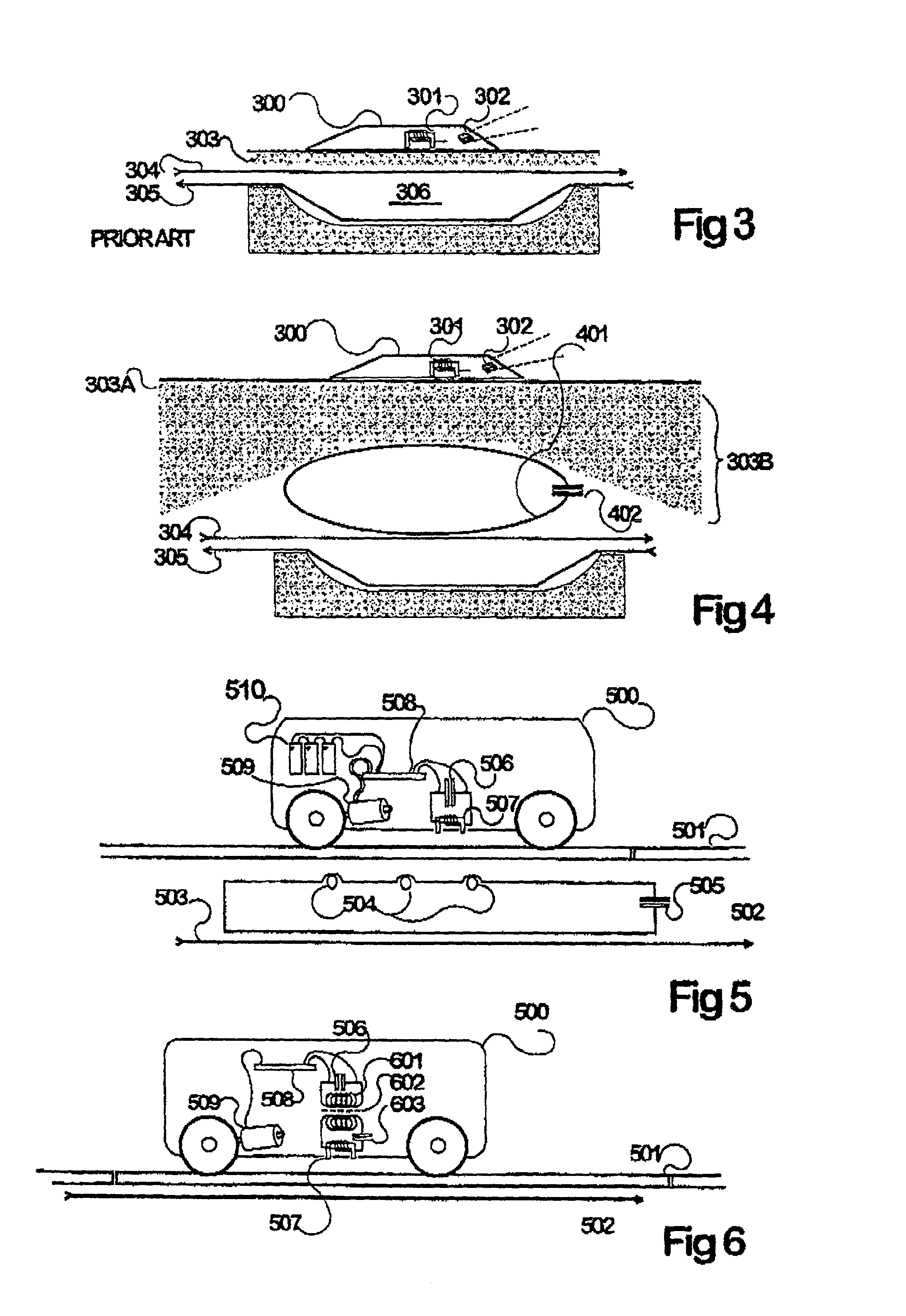
[0065] FIG. 3 shows a prior-art view of a road stud (which is a device including a resonant secondary circuit, a control circuit to limit secondary current, and an array of light-emitting diodes intended as a self-lit "cat's eye" type of lane marker), in which the stud 300 is simply glued onto a road surface 303 above a previously cut slit containing primary inductive pathway conductors 304 and 305. Typically, the conductors are spread apart within the space 306 so that the magnetic field surrounding the upper conductor 304 is not partially cancelled out by the reverse field in 305. Inside the road stud there is a pickup inductor 301 (here shows side-on), resonating circuitry, power control and supply circuitry and a bank of light-emitting diodes 302 to provide a useful output.

[0066] One problem with this device is that after the road receives each of an often needed re-sealing the distance over which the inductive field must travel to reach the stud becomes greater and ma...

application example 2b

Two Road Studs

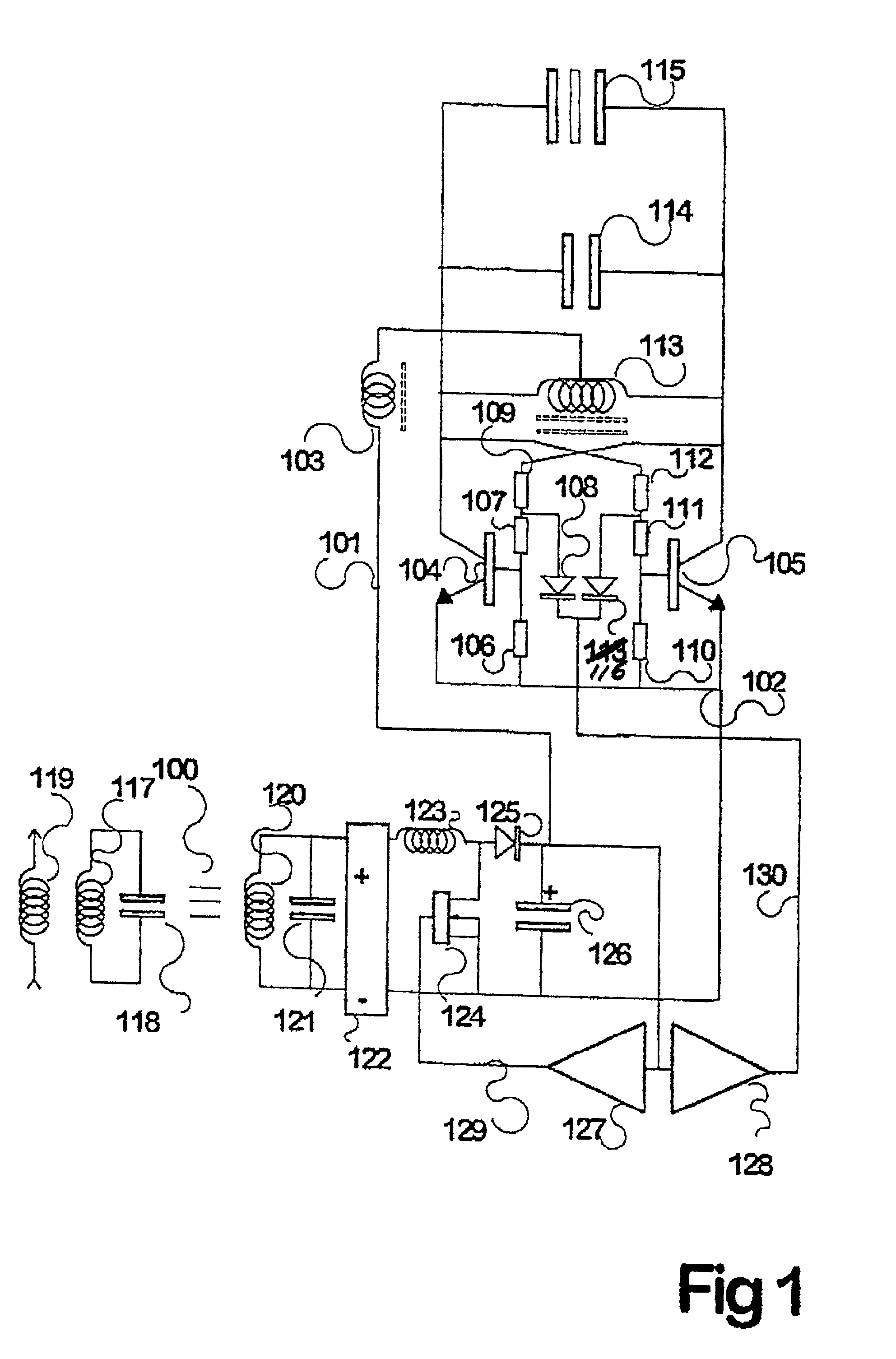
[0069] One road stud close to the primary conductor can act as a intermediate resonant circuit for another road stud; here the intermediate circuit is not a simple passive inductor / capacitor circuit but is controlled by a shorting switch arrangement for decoupling the circuit in the event of too high a circulating voltage. This illustrates use of an intermediate loop incorporating a current limiting feature. Such a feature is useful in permitting primary current to pass an un-loaded intermediate loop and so reach further consuming devices.

application example 3a

H AN INTERMEDIATE LOOP ATTACHED TO THE TRACKWAY

[0070] FIG. 5 shows a vehicle 500, capable for example of running along an arrangement of rails 501, in which an electric motor 509 drives at last one wheel; the motor being fed from a set of motor control circuitry 508 which accepts AC power from a resonant pickup circuit comprised of a capacitor 506 and an inductor 507 preferably having a ferromagnetic core arranged so as to effectively intercept a flux from a supply. The primary conductor 503 running substantially parallel to the track has as an intermediate coupling arrangement a loop of wire (preferably a litz wire, because it may carry a high resonating current) including optionally one or more discrete inductances 504 and a tuning capacitor 505. The inductances 504 have two functions; they aid in causing the loop to be electrically resonant at a system-wide resonant frequency, and they act as concentrated sources of inductive fields to be picked up by the vehicle. In some transpo...


PUM

PropertyMeasurementUnit
capacitanceaaaaaaaaaa
areaaaaaaaaaaa
sizeaaaaaaaaaa

Abstract

Inductive power transfer across an extended gap (100) from a primary conductor (119) is provided by means of a resonant intermediate loop comprised of capacitor (118) with inductor (117) carrying a larger resonating current, that can in turn generate an inductive field to be collected by a pickup coil (120). This process and device find application in an electroluminescent advertising panel.

Description

[0001] This application is a division of co-pending application Ser. No. 09 / 423,364, filed on Nov. 8, 1999, which is the national phase of PCT International Application No. PCT / NZ98 / 00053, filed on May 4, 1998, under 35 U.S.C. .sctn. 371. The entire contents of each of the above-identified applications are hereby incorporated by reference.[0002] This invention relates to a power supply for an electroluminescent display, and to the use of inductive power transfer to provide power across an extended gap between a primary inductive trackway and a secondary pickup device, for a range of purposes including motive power, battery charging and lighting, including lighting using electroluminescent panels.[0003] Inductive power transfer, although contactless, has in most applications in the prior art using primary pathways required that the configurations shall include ferromagnetic cores and that the secondary or pickup shall be quite closely placed in proximity to, or about the primary cond...

Claims


Application Information

Patent Timeline
Patent Type & Authority Applications(United States)
IPC IPC(8): H02J17/00B60L5/00B60L11/18B60M7/00H01F38/14H02J5/00H02M7/538H02M7/5381
CPCH01F38/14H02J5/005H02M7/5381H02M2001/007H02J7/0042H02J50/50H02J50/12H02J50/40H02M1/007
Inventor BOYS, JOHN TALBOT
Owner AUCKLAND UNISERVICES LTD
Why Eureka
Try Eureka