
Internal combustion engine

a combustion engine and combustion chamber technology, applied in the direction of engine starters, auxilary lubrication, muscle operated starters, etc., can solve the problems of difficult to reduce exhaust gas or emission gas, unsuitable for engine lubrication, and lubrication system using oil pumps

Inactive Publication Date: 2001-11-29
KIORITZ
View PDF2 Cites 11 Cited by
  • Summary
  • Abstract
  • Description
  • Claims
  • Application Information

AI Technical Summary

Benefits of technology

[0011] Another advantage of the present invention is to provide an internal combustion engine in which the amount of oil in a crank chamber can be optimized while making an engine lubrication structure simpler.
[0012] Another advantage of the present invention is to provide an internal combustion engine which does not require use of a check valve, such as a reed valve, as an indispensable component thereof.
[0013] Another advantage of the present invention is to provide an internal combustion engine which can effectively lubricate itself without requiring another power source.

Problems solved by technology

The two-stroke cycle engine of this type, however, has a disadvantage in that it is difficult to reduce the exhaust gas or an emission gas since the exhaust gas therefrom contains a fair amount of unburned gas constituent due to a gas-flow type scavenging system employed therein.
A lubrication system using the oil pump, however, is not suitable for an engine of the portable working machine since an additional mechanism for discharging and recovering the lubricating oil has to be employed and thus would make the system complicated and heavy.
On the other hand, a lubrication system using the oil dipper has shortcomings as well in that it is difficult to determine a length of the oil dipper during a designing stage of the engine.
That is, if the length of the oil dipper is designed to be too short, a desired degree of oil lubrication may become difficult to be supplied by the oil dipper within a short period of time after starting due to an oil consumption.
On the contrary, if the length of the oil dipper is designed to be too long, a large amount of oil may be splashed up by the oil dipper immediately after the oil has been filled into the oil pan making a mist of oil in the crank chamber too rich (to reach to excessive level) possibly resulting in a problematic level of pollution created by the blow-by gas.
Hei 10-288019, Hei 10-288020, or Hei 9-170417 uses a check valve such as a reed valve as an indispensable component, the reed valve is likely to result in problems associated with its durability since this type of engine is driven at an extremely high speed, that is, even the normal revolution number of which is as high as 7500 rpm, and in addition, there is another risk in the high revolution driving range that the valve may possibly fail to operate as intended in the design stage because the valve is likely to be kept substantially open all the time.

Method used


Image

  • Internal combustion engine
  • Internal combustion engine
  • Internal combustion engine

Examples


Embodiment Construction

[0024] Preferred embodiments of the present invention will now be described in detail with reference to the attached drawings.

[0025] Initial Embodiment (FIG. 1 to FIG. 4)

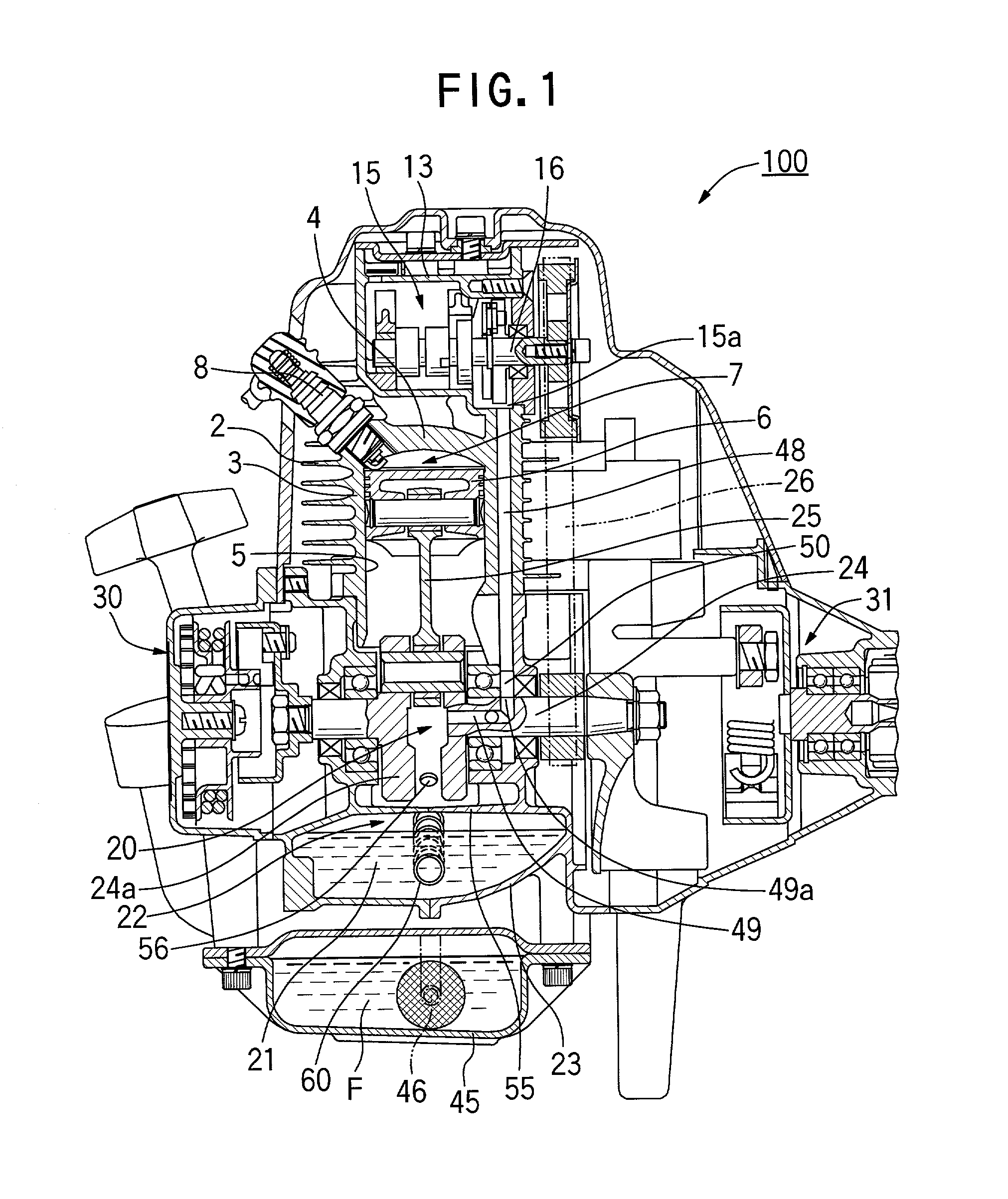
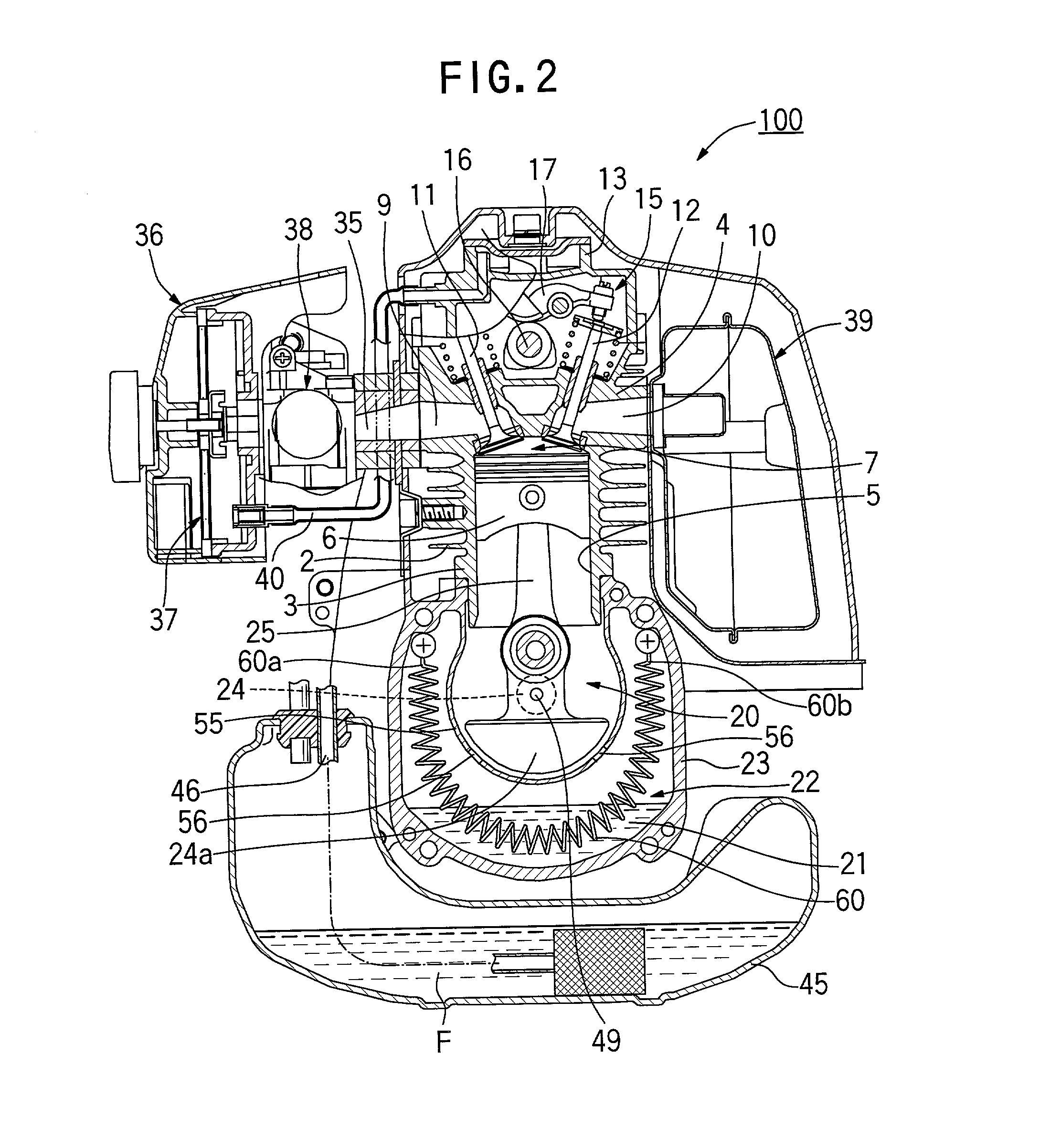
[0026] An engine 100 shown in FIGS. 1-4 is of a relatively compact type with a displacement of about 20 to 50 ml, which may be employed, for example, as a power source for a portable trimmer. The engine 100 comprises a cylinder block 3 with cooling fins 2 formed thereon for air-cooling, and a cylinder head 4 disposed thereon, wherein a combustion chamber 7 is defined between the cylinder head 4 and a piston 6 fittingly inserted into a cylinder bore 5 formed in the cylinder block 3 to be slidably movable in an up-and-down direction.

[0027] The cylinder head 4 is equipped with an ignition plug 8 (FIG. 1) arranged to face the combustion chamber 7, and an intake port 9 and an exhaust port 10 each opening to the combustion chamber 7 (FIG. 2), wherein the intake port 9 is opened and closed by an intake valve 11 while the e...


PUM


Abstract

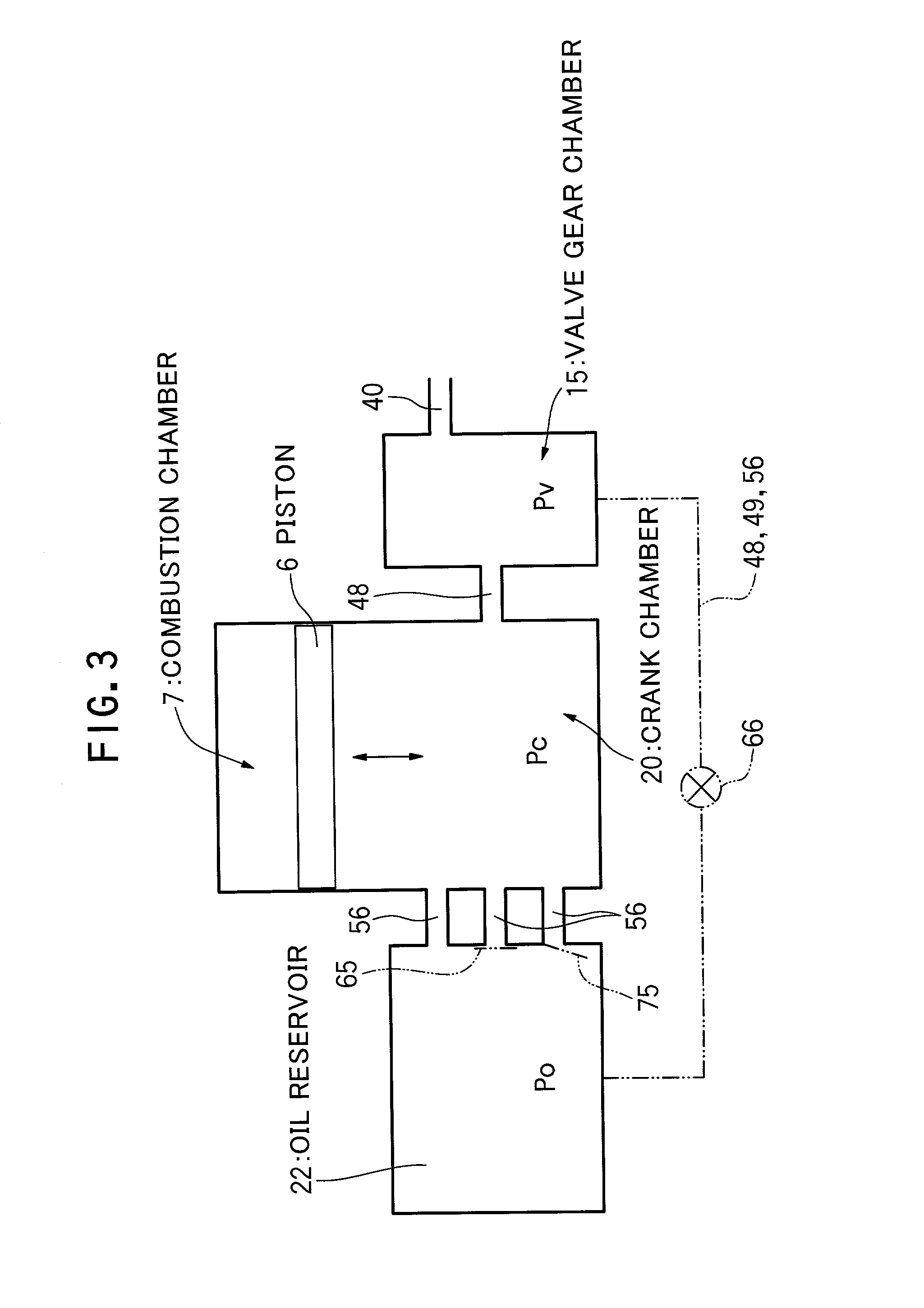
An internal combustion engine capable of optimizing the amount of oil in the crank chamber with a simplified structure of lubrication system, in which a U-shaped oil reservoir is formed surrounding and adjacent to a crank chamber. At least one small hole is formed on a partition wall which separates the oil reservoir and the crank chamber from each other so that the crank chamber may always communicate with the oil reservoir through the small hole. Due to a flow resistance in the small hole, a pressure Po in the oil reservoir changes following a change of pressure Pc in the crank chamber with some delay, and where the pressure difference between the oil reservoir and the crank chamber caused by a delay in the change of the pressure Po in the oil reservoir, results in the introduction of the oil in the oil reservoir into the crank chamber. It further allows excessive oil in the crank chamber to be circulated back into the oil reservoir.

Description

[0001] The present invention generally relates to an internal combustion engine and in particular, to an engine with excellent lubricity suitable for a power source of a small working machine including but not limited to a portable trimmer, a lawn mower, a chain saw or the like.DESCRIPTION OF THE PRIOR ART[0002] A portable type working machine represented by a portable trimmer as well as a chain saw is required to allow an operator to work without any restrictions on his working posture. Accordingly, an internal combustion engine as a power source mounted on such working machine must provide stable operation even if the machine is used in the working posture of, for example, a laterally tilted position.[0003] In order to meet this requirement, there has been employed conventionally a compact air-cooled type two-stroke cycle gasoline engine (hereafter, the "two-stroke cycle engine") equipped with a diaphragm carburetor, which uses a mixed fuel oil composed of fuel and lubricant oil m...

Claims


Application Information

Patent Timeline
IPC IPC(8): F01M1/04F01M1/06F01M1/12F01M11/06
CPCF01M1/04F01M2001/126
Inventor NAGAI, NOBORULIU, YUMIN
Owner KIORITZ
Learn More