
Apparatus and method for focusing ions and charged particles at atmospheric pressure

Inactive Publication Date: 2002-01-31
SHEEHAN EDWARD W +1
View PDF0 Cites 48 Cited by
  • Summary
  • Abstract
  • Description
  • Claims
  • Application Information

AI Technical Summary

Problems solved by technology

As a consequence of a wide variety of dispersive processes, efficient sampling of ions from atmospheric pressure sources to small cross-sectional targets or through small cross-sectional apertures and tubes (usually less than 1 mm) into a mass spectrometer becomes quite problematic.
This general approach in severely restricted by the need for precise aperture alignment and source positioning and very poor sampling efficiency.
This approach to focusing ions from atmospheric sources is limited by the acceptance angle of the field generated by the cone.
As with planar apertures, source positioning relative to the aperture is critical to performance and collection efficiency is quite low.
This configuration has a clear disadvantage in that the potential well resulting from the field penetration is not independent of ion source position, or potential.
High voltage needles can diminish this well.
Larger flow sources become less efficient and problematic.
This device had limitations with duty cycle of ion collection in a modulating field (non-continuous sample introduction) and spacial and positioning restrictions relative to the sampling aperture.
Although the approach is similar to the present device in concept, it is severely limited by gas discharge that may occur at low pressures if higher voltages are applied to the electrodes and most of the ions are lost at the cone-aperture from atmospheric pressure into the first pumping stage.
These devices generally are not continuous, nor do they require focusing at extremely high compression ratios.
No existing technology has positional independence of the source.

Method used


Image

  • Apparatus and method for focusing ions and charged particles at atmospheric pressure
  • Apparatus and method for focusing ions and charged particles at atmospheric pressure
  • Apparatus and method for focusing ions and charged particles at atmospheric pressure

Examples


Embodiment Construction

[0035] FIGS. 1A and 6A (Basic Focusing Device)

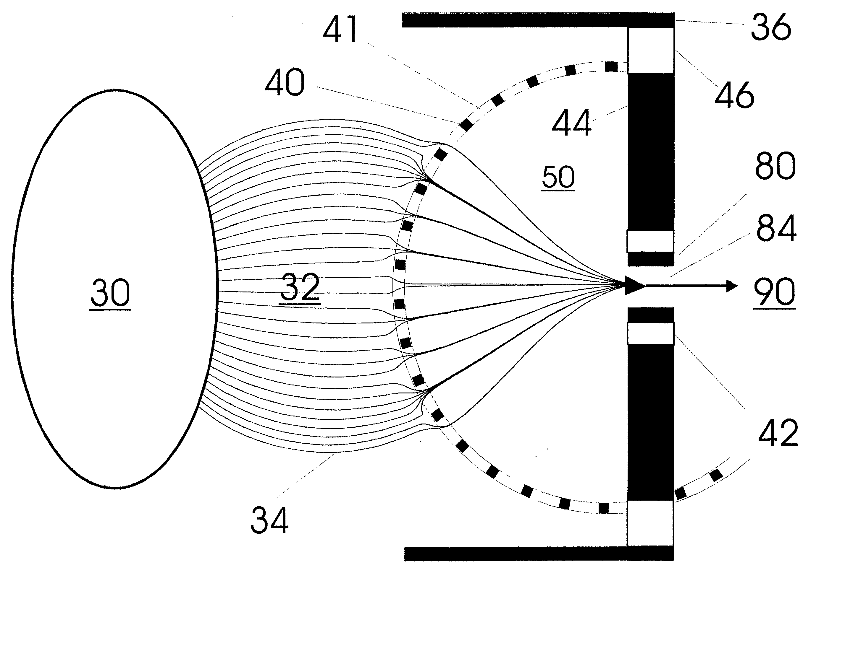
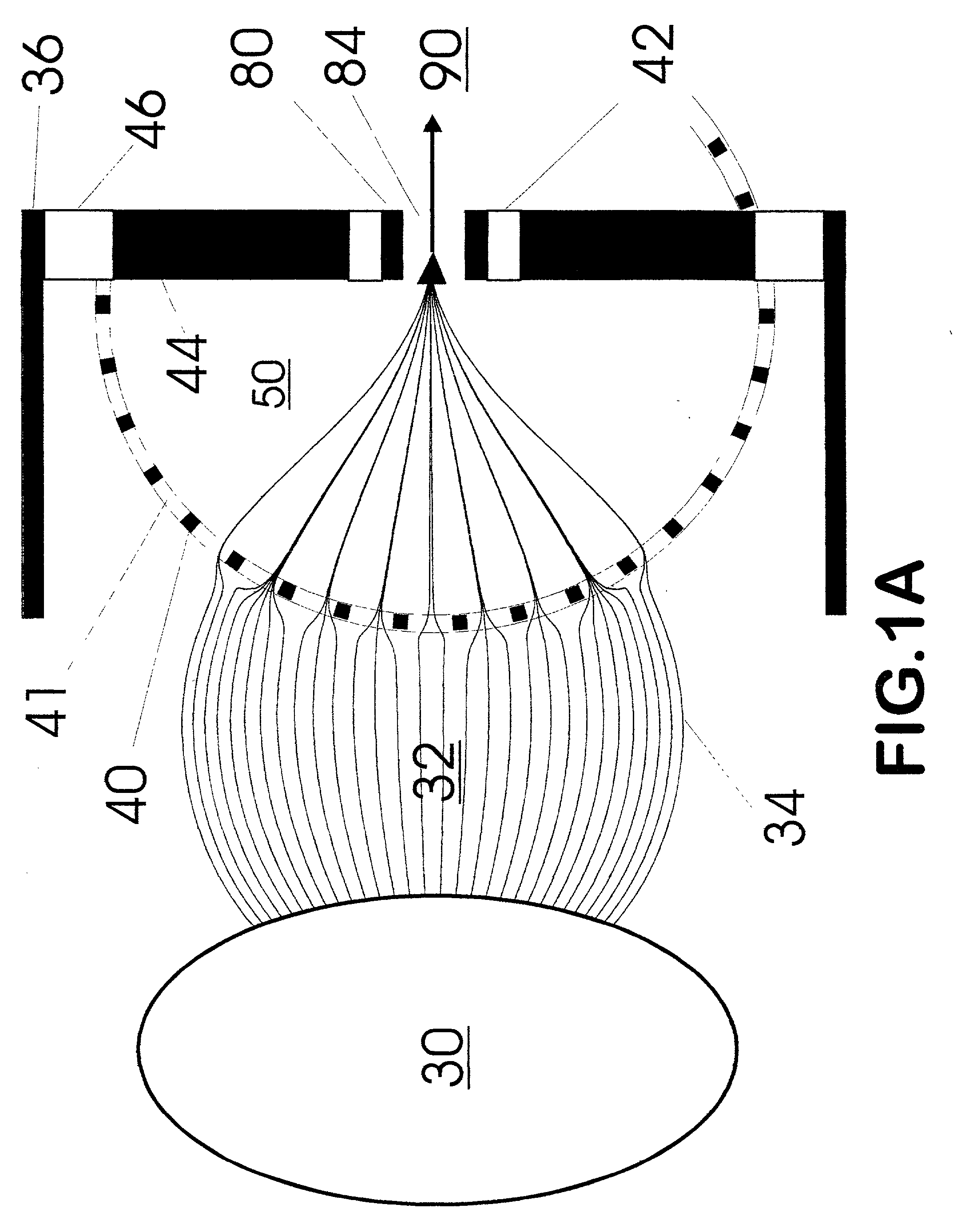
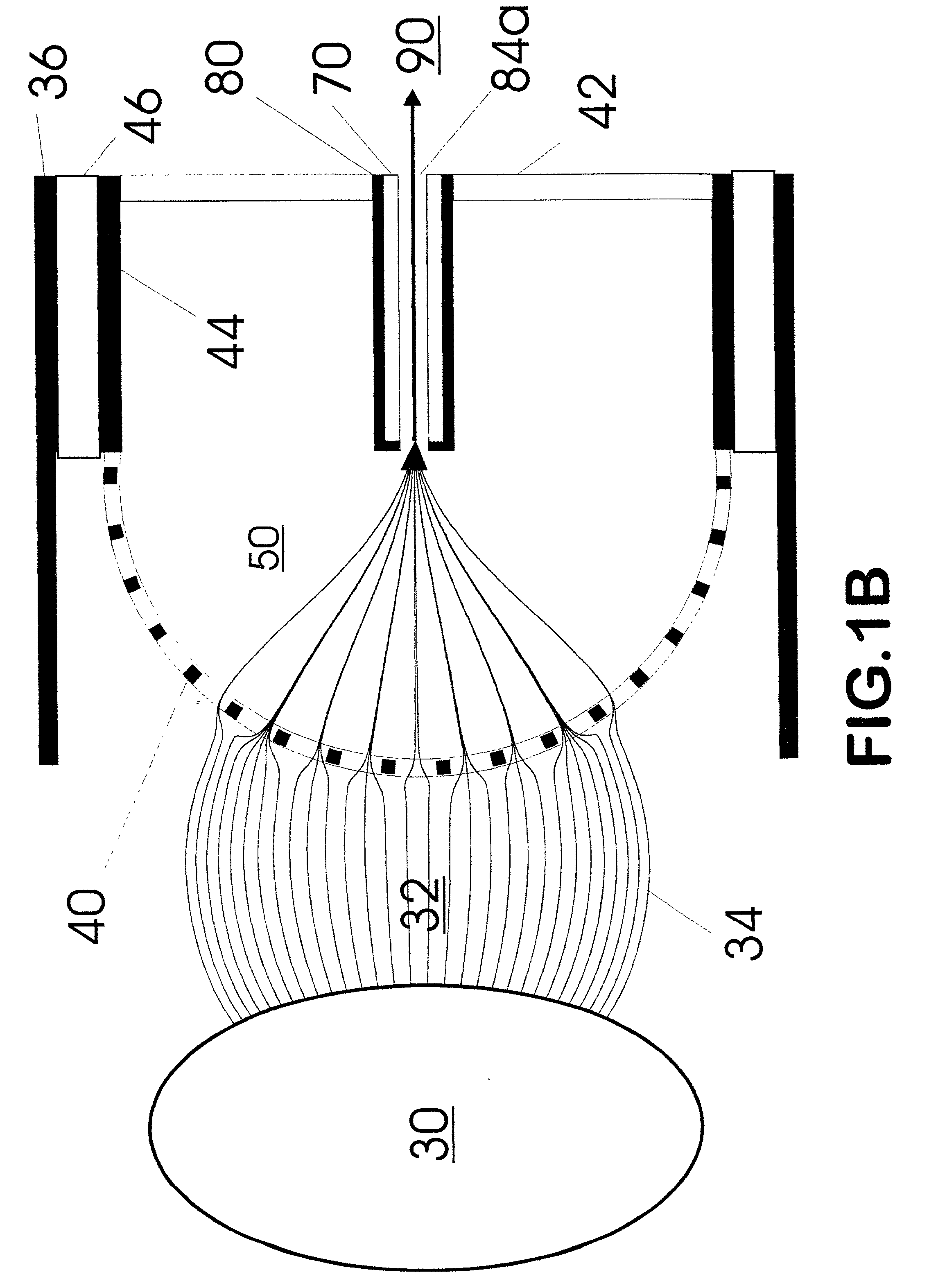
[0036] One embodiment of the present invention is an ion or particle focusing device utilizing a high transmission element 40 as illustrated in FIG. 1A. The device includes an atmospheric pressure or near atmospheric pressure ion source region 30 from which ions are supplied to an ion collection region 32. This device is intended for use in collection and focusing of ions from a wide variety of ion sources; including, but not limited to electrospray, atmospheric pressure chemical ionization, photo-ionization, electron ionization, laser desorption (including matrix assisted), inductively coupled plasma, and discharge ionization. Both gas-phase ions and charged particles emanating from region 30 are collected and focused with this device. Ions and charged particles from region 32 move through a high transmission element 40 into an ion focusing-steering region 50. Strong electric fields in region 50 relative to region 32 cause ions in regio...


PUM


Abstract

Improvements have been made for collection and focusing of ions generated from atmospheric pressure sources such as electrospray, atmospheric pressure chemical ionization, inductively coupled plasma, discharge, photoionization and atmospheric pressure matrix assisted laser desorption ionization. A high transmission electro-optical surface is placed between the source regions and the focusing regions to optimize the field geometries and strengths in each respective region. Compression ratios of greater than 5000 are capable of transferring virtually all ions from large volume dispersive ion regions into ion beam cross-sections of less than 1 mm. Embodiments of this invention are methods and devices for improving sensitivity of mass spectrometry when coupled to atmospheric pressure ionization sources.

Description

[0002] 1. Field of Invention[0003] This invention relates to methods and devices for improved collection and focusing of ions generated at atmospheric pressure for introduction into the mass spectrometer and other particle detectors.[0004] 2. Description of Prior Art[0005] The generation of ions at atmospheric pressure is accomplished by a variety of means; including, electrospray (ES), atmospheric pressure chemical ionization (APCI), atmospheric pressure matrix assisted laser desorption ionization (MALDI), discharge ionization, .sup.63Ni sources, inductively coupled plasma ionization, and photoionization. A general characteristic of all atmospheric sources is the dispersive nature of the ions once produced. Needle sources such as electrospray and APCI disperse ions radially from the axis in high electric fields emanating from needle tips. Aerosol techniques disperse ions in the radial flow of gases emanating from tubes and nebulizers. Even desorption techniques such as atmospheric ...

Claims


Application Information

Patent Timeline
IPC IPC(8): H01J49/04
CPCH01J49/067
Inventor SHEEHAN, EDWARD W.WILLOUGHBY, ROSS C.
Owner SHEEHAN EDWARD W
Learn More