
Ion enrichment aperture arrays

a technology of aperture arrays and apertures, which is applied in the direction of electron/ion optical arrangements, particle separator tube details, separation processes, etc., can solve the problems of low electrostatic field penetration into the lower pressure region relative to larger apertures with higher conductance, and more sensitive response of ion analyzers or higher currents, so as to achieve high transmission, maximum ions transmission, and low dispersion of ions

Inactive Publication Date: 2004-12-09
CHEM SPACE ASSOIATES
View PDF3 Cites 67 Cited by
  • Summary
  • Abstract
  • Description
  • Claims
  • Application Information

AI Technical Summary

Benefits of technology

[0020] The objective of the present invention is to maximize the transmission of ions from one pressure regime into an adjacent lower pressure region through an array of apertures in a laminated lens while minimizing the conductance of gas from the higher pressure into the lower pressure region. The relatively uniform electrostatic field through the laminated lens assures high transmission and low dispersion of the ions while in the conductance pathways of the lens. This condition does not exist in present-day ion conductance pathways in atmospheric or high pressure interfaces for mass spectrometers and will result in significantly higher ion transmission through conductance paths compared to the current art.
[0021] An important advantage of the device is the operation at lower gas loads into the lower pressure regions while maintaining the transmission of ions. This has beneficial implications including lower requirements for pumping, power, and general size. Conversely, this device has higher transmission of ions for a given total gas load on the lower pressure region resulting in more sensitive response for ion analyzers or higher currents for current deposition processes. Utilizing small apertures in the arrays results in very low electrostatic field penetration into the lower pressure region relative to larger apertures with higher conductance.
[0022] Another important advantage of the present device is the decrease in contamination from sample deposition along the conductance path and the associated reduction in required maintenance, system drift, charging, and potential carryover from sample to sample due to deposition.
[0023] An important object of the present invention is the use of matched ion optics to the conductance pattern. The macroscopic lenses can be patterned to focus the ions to a microscopic compressed pattern of conductance opening. In other words, with patterned arrays we can focus the ions to an exact pattern of conductance openings rather than being required to focus to a single opening of a tube or aperture.
[0024] Another important advantage of conductance arrays is the ability to measure the transmission of ions in discrete packets, each representative of a portion of the delivered cross-section from a source of ions. With this capability we are able to independent measure each pathway to discern the cross-section composition of a source of ions. This increased information content adds a enhance dimension to analysis where composition across a cross-section may provide diagnostic, feedback, or analytical information.

Problems solved by technology

Conversely, this device has higher transmission of ions for a given total gas load on the lower pressure region resulting in more sensitive response for ion analyzers or higher currents for current deposition processes.
Utilizing small apertures in the arrays results in very low electrostatic field penetration into the lower pressure region relative to larger apertures with higher conductance.

Method used


Image

  • Ion enrichment aperture arrays
  • Ion enrichment aperture arrays
  • Ion enrichment aperture arrays

Examples


Embodiment Construction

. 1 AND 2--PREFERRED EMBODIMENT

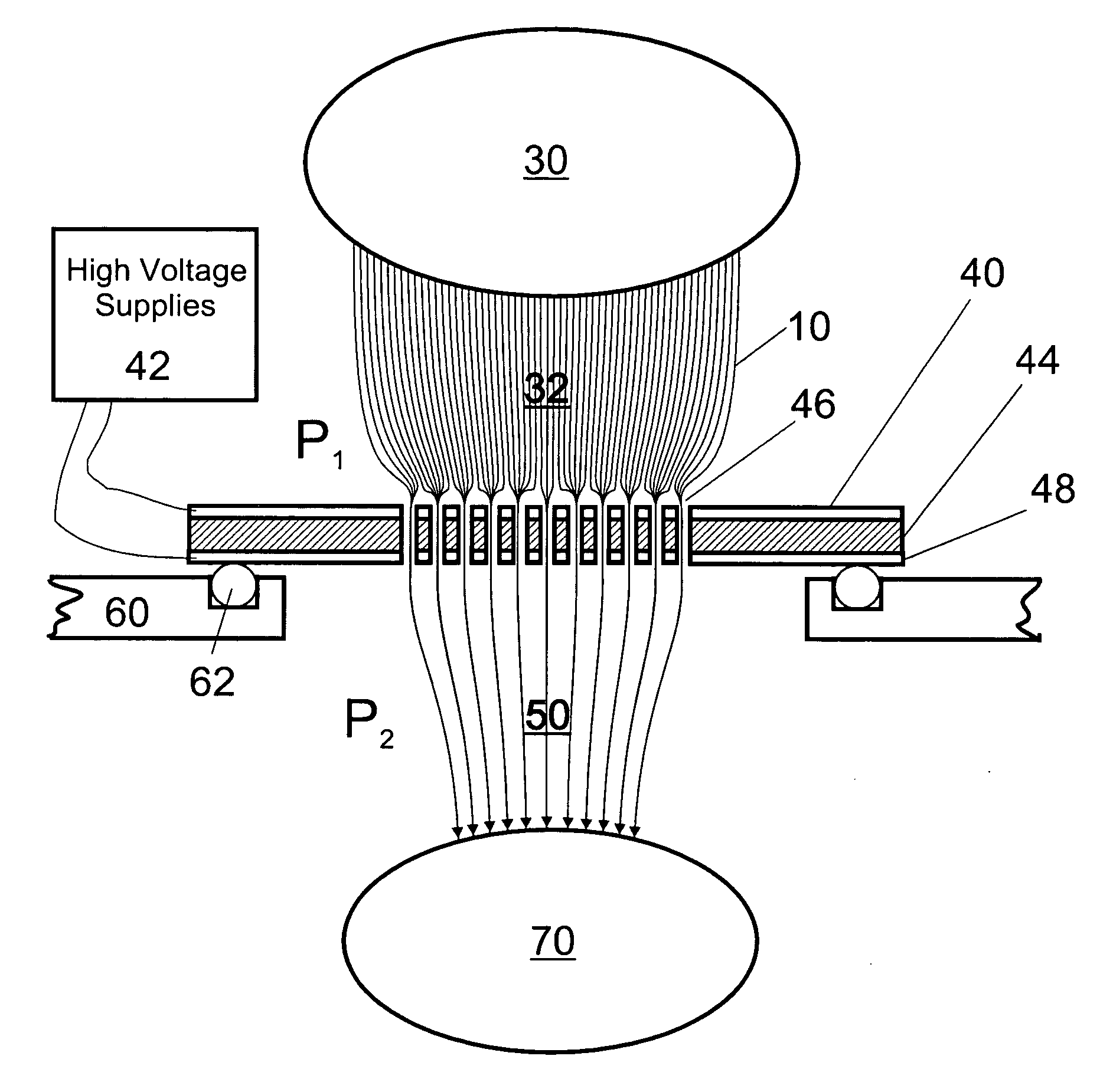
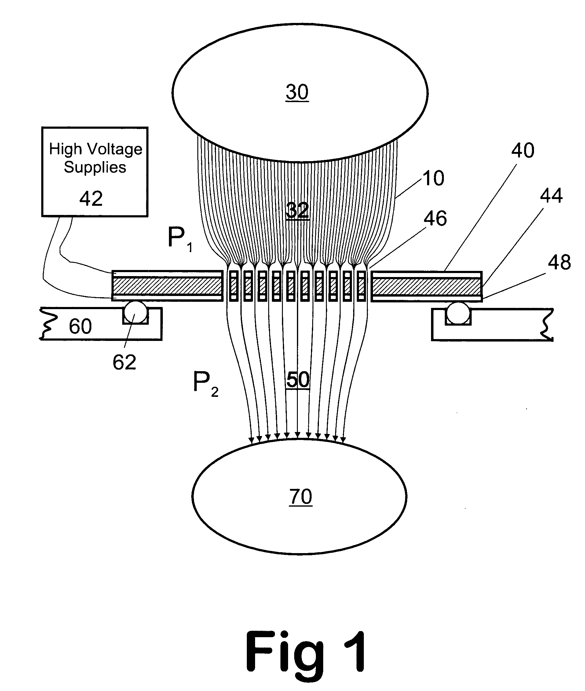
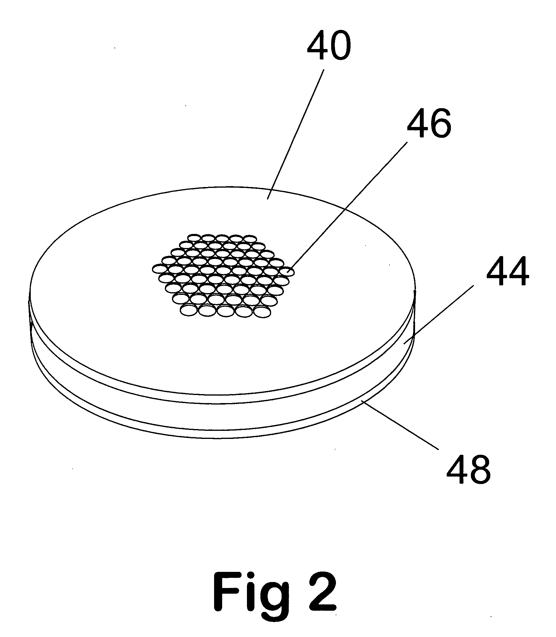
[0066] A preferred embodiment of the ion selective multi-aperture laminate of the present invention is illustrated in FIGS. 1 and 2. The multi-aperture laminate has a thin first insulated laminate 44 of uniform cross section consisting of an insulating material. A layer of metal 40 and 48 is laminated on both sides of the laminate 44. In the preferred embodiment, 44 is an insulating material, such as glass or ceramic. However, it can consist of any other material that can isolate electrically the two metal laminates 40 and 48 from each other, such as nylon, polyimide, Teflon, poly ether ether ketone (PEEK), etc.

[0067] The multi-aperture lens is populated with many holes or apertures 46 that traverse the lens leading from higher pressure ion collection region 32 to lower pressure region 50. The inlets of the apertures 46 are downstream of the ion source region 30 and ion collection region 32. The inlets accept ions from the region 32. The ions are trans...


PUM


Abstract

Improvements have been made for collecting, focusing, and directing of ions and / or charged particles generated at atmospheric or near atmospheric pressure sources, such as but not limited to, electrospray; atmospheric pressure discharge ionization, chemical ionization, photoionization, and matrix assisted laser desorption ionization; and inductively coupled plasma ionization. A multiple-aperture laminated structure is place at the interface of two pressure regions. Electric fields geometries and strengths across the laminated structure and diameters of the apertures; all of which act to optimize the transfer of the ions from the higher pressure region into the lower pressure region while reducing the gas-load on the lower pressure region. Embodiments of this invention are methods and devices for improving sensitivity of mass spectrometry when coupled to atmospheric, near atmospheric, or higher pressure ionization sources by reducing the gas-load on the vacuum system.

Description

[0001] This application is entitled to the benefit of Provisional Patent Application Ser. No. 60 / 476,582, filed 2003, June 7. This application is related to Provisional Patent Application Ser. No. 60 / 210,677, filed 2000, June 9 and patent application Ser. No. 09 / 877,167, filed 2001, June 8, now U.S. Pat. No. 6,744,041, issued 2004, June 1; Provisional Patent Application Ser. No. 60 / 293,648, filed 2001, May 26, now patent application Ser. No. 10 / 155,151, filed 2002, May 25; Provisional Patent Application Ser. No. 60 / 384,869, filed 2002, June 1, now patent application Ser. No. 10 / 499,147, filed 2003, May 31; Provisional Patent Application Ser. No. 60 / 410,653, filed 2002, September 13, now patent application Ser. No. 10 / 661,842, filed 2003, September 12; Provisional Patent Application Ser. No. 60 / 419,699, filed 2002, October 18, now patent application Ser. No. 10 / 688,021, filed 2003, October 17; and Provisional Patent Application Ser. No. 60 / 476,576, filed 2003, June 7. Each of the abo...

Claims


Application Information

Patent Timeline
Patent Type & Authority Applications(United States)
IPC IPC(8): B01DB01D59/44H01J49/00H01J49/06H01J49/10
CPCH01J49/067H01J49/0404
Inventor SHEEHAN, EDWARD W.WILLOUGHBY, ROSS C.
Owner CHEM SPACE ASSOIATES
Learn More