Radio frequency power generator

Active Publication Date: 2006-01-26
AGILENT TECH AUSTRALIA M
View PDF13 Cites 64 Cited by
  • Summary
  • Abstract
  • Description
  • Claims
  • Application Information

AI Technical Summary

Benefits of technology

[0010] In an RF generator, according to the present invention, the feedback control circuit can have an operating time delay in the microseconds range (eg. 10-20 μs) whereas the time delay associated with significant load impedance changes (for example from unexpected extinguishment of the plasma) will typically occur much more slowly (for example in milliseconds). Thus the non-constant load impedance conditions that can occur for an RF power generator for an ICP can be handled without detriment to the generator circuit by providing a feedback response time that is many times (for example 1000 times) faster than the rate of change in the load conditions. Thus an RF power generator according to the invention allows for controlled overload behaviour by inclusion of a feedback control circuit that allows a feedback response time that is very fast compared to the rate of change of the load conditions. Different types of feedback control circuits that allow this control are possible. Examples of such circuits are described below.
[0011] Also, an RF power generator, according to the present invention, may be constructed f

Problems solved by technology

Another significant factor is the cost of RF generator in a spectrometry instrument.
Spectrometry instrumentation is expensive and the field is competitive, thu

Method used


Image

  • Radio frequency power generator
  • Radio frequency power generator
  • Radio frequency power generator

Examples


Embodiment Construction

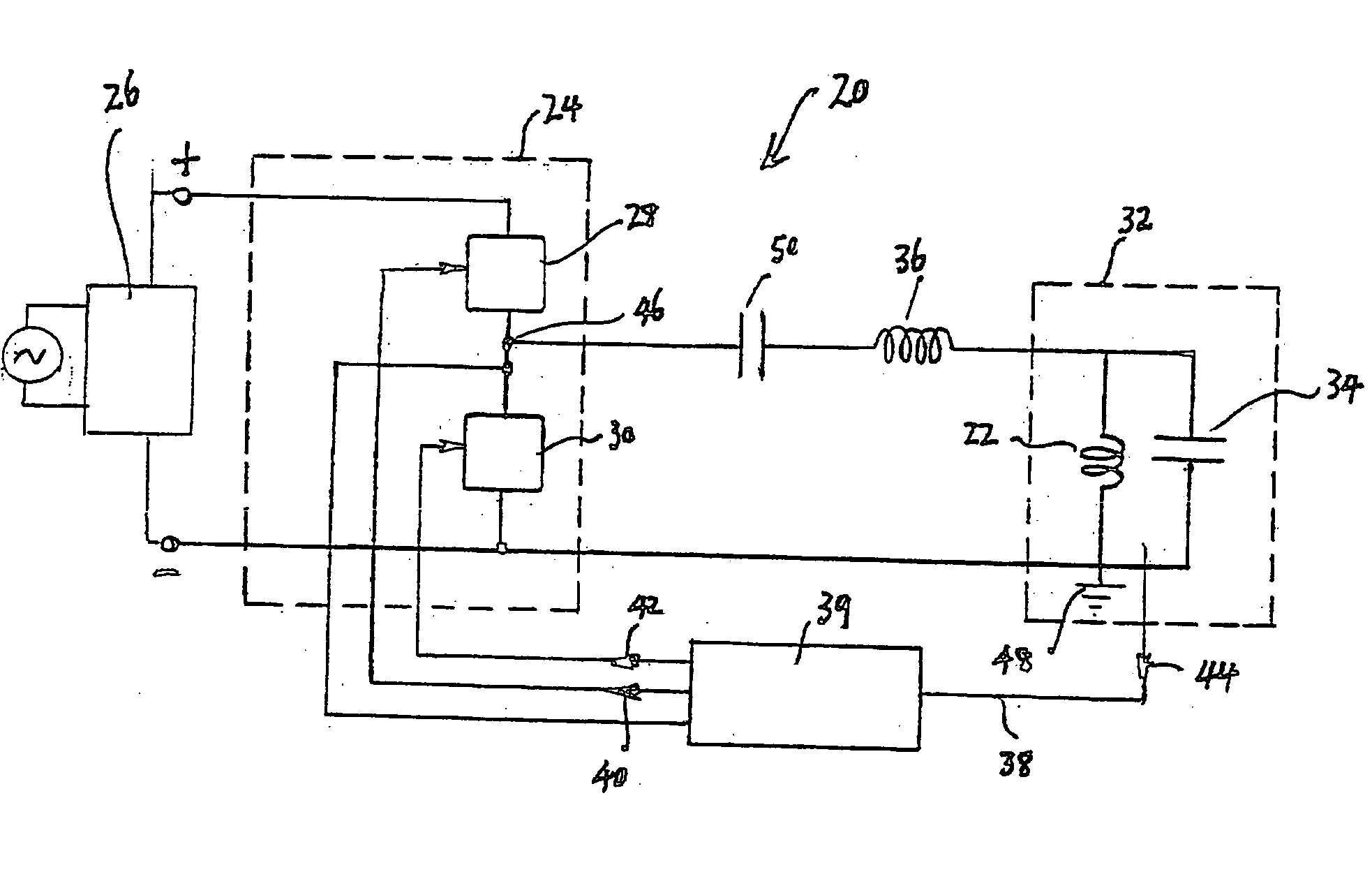
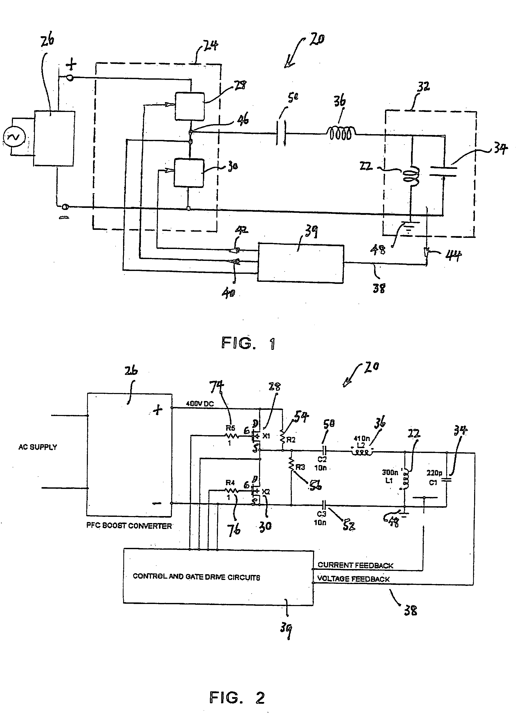
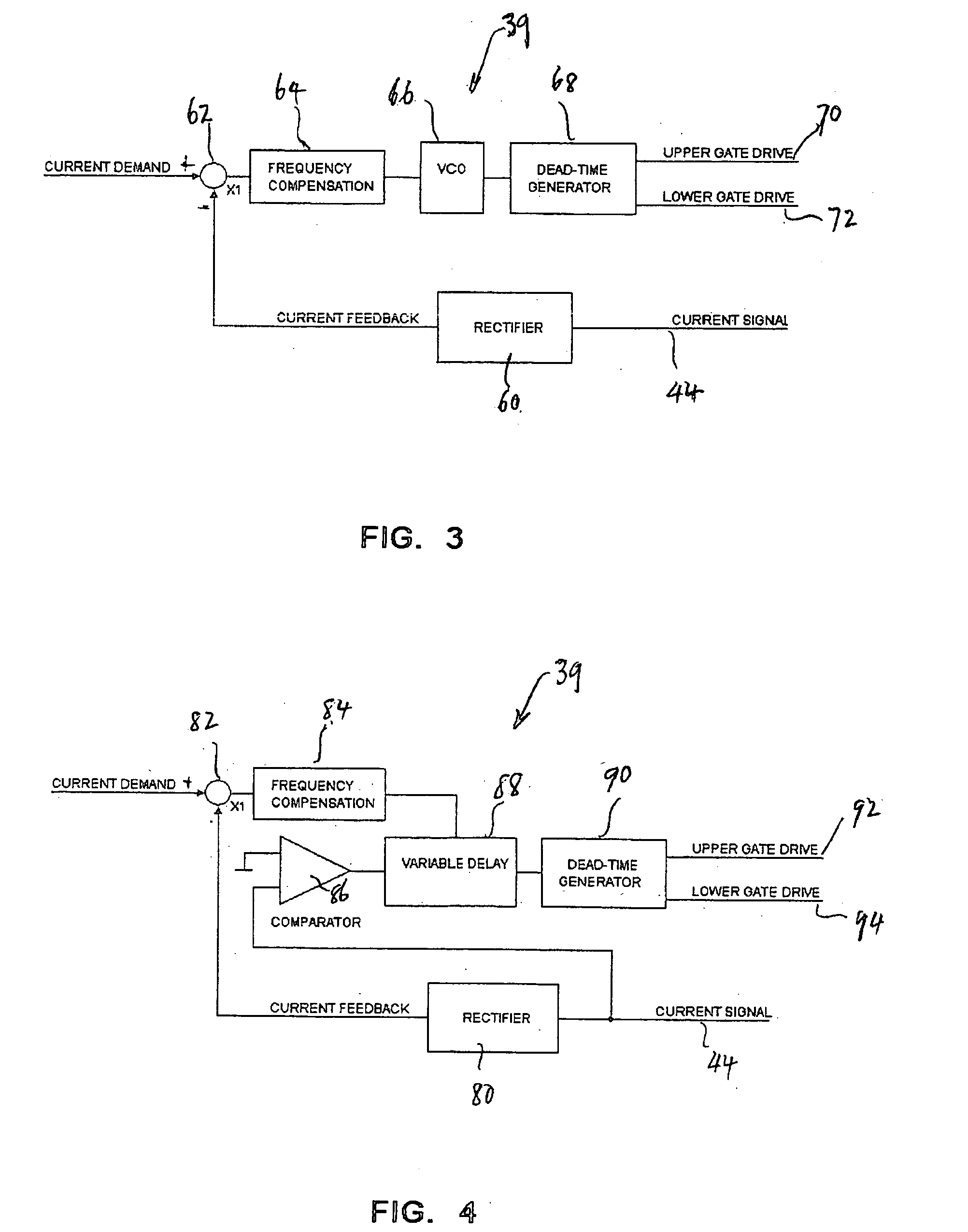
[0028] With reference to FIG. 1, an RF power generator 20 according to an embodiment of the invention includes an induction coil 22 for exciting an inductively coupled plasma (ICP) for spectrometry. As is known, the induction coil 22 is typically coaxial with a plasma torch (not shown) through which a plasma forming gas, typically argon, is passed at a controlled flow rate. The generator 20 comprises a switching circuit 24 that is connectable across a DC voltage supply which is preferably an AC to DC converter as indicated at 26. The switching circuit 24 includes first and second solid state switching devices 28 and 30 in a half bridge configuration. The induction coil 22 is part of a load circuit 32 that also includes a capacitor 34 in parallel with the induction coil 22. The load circuit 32 is grounded at 48. RF power from the switching circuit 24 is coupled to the load circuit 32 by an inductor 36 and blocking capacitor 50. The impedances of load circuit 32 plus the inductor 36 a...


PUM


Abstract

A RF power generator for exciting inductively coupled plasma for spectrometry includes an induction coil for exciting the plasma as part of its load circuit. The load circuit also comprises a capacitor connected in parallel with the induction coil. The RF power generator is a free running oscillator having a switching circuit of two MOSFETs alternately switchable on and off via a feedback control circuit from the load circuit. RF power from the switching circuit is coupled to the load circuit via an inductor. The inductor and load circuit is resonant at a first frequency, which is lower than the operating frequency of the power generator.

Description

CROSS REFERENCE TO RELATED APPLICATION [0001] This application claims the benefit of Australian Provisional Application No. 2004904062 filed Jul. 22, 2004. BACKGROUND OF THE INVENTION [0002] The present invention relates to a radio frequency (RF) electrical power generator that includes an induction coil for exciting inductively coupled plasma (ICP) for use in spectrometry. [0003] In spectrometry, an ICP may be used as a source of ions for mass spectrometry (MS) or as a source of light for atomic optical emission spectrometry (OES). The ICP apparatus typically consists of one or more water-cooled induction coils mounted coaxially with a torch assembly through which argon gas is introduced at carefully controlled rates. RF electrical power is supplied to the induction coils. The argon does not conduct electricity and so is not heated by the RF electromagnetic field of the induction coils until the plasma is “struck”, typically by a small electrical discharge created in the argon by a...

Claims


Application Information

Patent Timeline
IPC IPC(8): H01J7/24H05B31/26
CPCH01J37/321H01J37/32174H02M7/538H03H7/09H03H7/427Y02B70/1441H03H7/175H03H7/1775H05H1/36Y02B70/10
Inventor STEVENSON, HUGH CHARLES
Owner AGILENT TECH AUSTRALIA M
Why Eureka
Try Eureka