Endoscope system having multiaxial-mode laser-light source or substantially producing multiaxial-mode laser light from single-axial-mode laser light

a laser light source and endoscope technology, applied in the field of endoscope systems, can solve the problems of inability to accurately discriminate the properties of living tissue, uniaxial intensity of excitation light applied to living tissue, and production of interference patterns

Inactive Publication Date: 2002-03-28
FUJIFILM HLDG CORP +1
View PDF14 Cites 43 Cited by
  • Summary
  • Abstract
  • Description
  • Claims
  • Application Information

AI Technical Summary

Problems solved by technology

When living tissue is illuminated with excitation light in order to display an image based on the intensity of fluorescence light emitted in response to the illumination, the intensity of the excitation light applied to the living tissue is not uniform since the surfaces of the living tissue are uneven.
That is, it is not possible to accurately discriminate properties of the living tissue based on only the intensity of the fluorescence light emitted in resp

Method used


Image

  • Endoscope system having multiaxial-mode laser-light source or substantially producing multiaxial-mode laser light from single-axial-mode laser light
  • Endoscope system having multiaxial-mode laser-light source or substantially producing multiaxial-mode laser light from single-axial-mode laser light
  • Endoscope system having multiaxial-mode laser-light source or substantially producing multiaxial-mode laser light from single-axial-mode laser light

Examples


first embodiment

[0056] Construction of First Embodiment

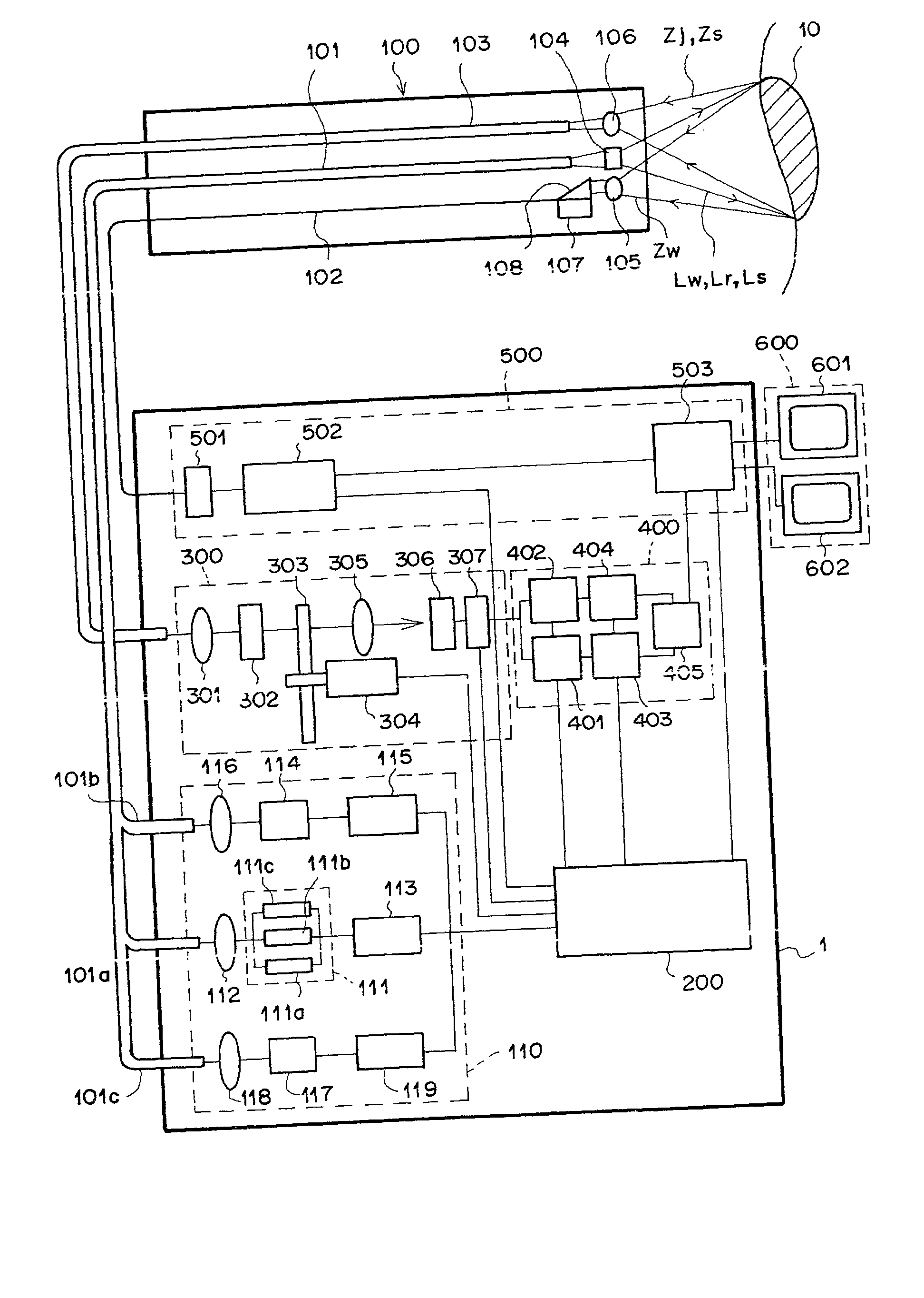
[0057] The first embodiment of the present invention is explained below. FIG. 1 is a diagram illustrating an outline of a construction of the fluorescence endoscope system as the first embodiment of the present invention. The fluorescence endoscope system of FIG. 1 realizes the functions of both the first and fifth aspects of the present invention. The fluorescence endoscope system of FIG. 1 comprises an image-information processing unit 1, an endoscope insertion unit 100, and a monitor unit 600. The endoscope insertion unit 100 is inserted into a portion of interest in a body of a patient. The image information processing unit 1 processes image information obtained from living tissue 10, and outputs processed image information. The monitor unit 600 displays a visible image based on the image information processed by the image information processing unit 1.

[0058] Specifically, the image information processing unit 1 comprises an illumination un...

second embodiment

[0087] Second Embodiment

[0088] The second embodiment of the present invention is explained below. FIG. 4 is a diagram illustrating an outline of a construction of the fluorescence endoscope system as the second embodiment of the present invention. In FIG. 4, elements having the same reference numbers as FIG. 1 have the same functions as the corresponding elements in FIG. 1, and explanations of the functions of the common elements are not repeated below. The fluorescence endoscope system of FIG. 4 realizes the functions of both the second and sixth aspects of the present invention. The fluorescence endoscope system of FIG. 4 is different from the fluorescence endoscope system of FIG. 1 in the light sources of the white light Lw and the excitation light Lr. That is, the fluorescence endoscope system of FIG. 4 comprises an illumination unit 120 instead of the illumination unit 110.

[0089] The illumination unit 120 comprises a white-light source 128 instead of the white-light source 111,...

third embodiment

[0094] Third Embodiment

[0095] The third embodiment of the present invention is explained below. FIG. 6 is a diagram illustrating an outline of a construction of the fluorescence endoscope system as the third embodiment of the present invention. In FIG. 6, elements having the same reference numbers as FIG. 1 have the same functions as the corresponding elements in FIG. 1, and explanations of the functions of the common elements are not repeated below. The fluorescence endoscope system of FIG. 6 realizes the functions of both the third and seventh aspects of the present invention.

[0096] The fluorescence endoscope system of FIG. 6 is different from the fluorescence endoscope system of FIG. 1 in that a vibrator (or shaker) 135 is attached to the white-light guide 101a, a vibrator (or shaker) 132 is attached to the excitation-light guide 101b, and controllers 136 and 133 for the vibrators 135 and 132 are provided. In addition, the fluorescence endoscope system of FIG. 6 comprises a white...


PUM


Abstract

In an endoscope system including: a light emission unit emits laser light as illumination light or excitation light; a light guide unit guides the illumination light or the excitation light to an object; and an image pickup unit picks up a normal image formed with reflection light generated by reflection of the illumination light from the object or a fluorescence image emitted from the object in response to the excitation light. The laser light is multiaxial-mode laser light, or the light emission unit includes a plurality of laser-light sources which emit single-axial-mode laser beams having different wavelengths or phases. Alternatively, a vibration unit which vibrates the light guide unit is provided, or a high-frequency signal is superimposed on a driving current of the light emission unit, so that the wavelength of the laser light is shifted among a plurality of values.

Description

[0001] 1. Field of the Invention[0002] The present invention relates to an endoscope system which illuminates living tissue with illumination light or excitation light, detects reflection of the illumination light from the living tissue or fluorescence light emitted from the living tissue in response to the illumination of the excitation light, and displays an image indicating information on the living tissue.[0003] 2. Description of the Related Art[0004] Endoscopes have been widely used for observing internal parts of living bodies, and treating diseased areas of the living bodies while observing the diseased areas. Recently, the following techniques have been proposed for the endoscope systems:[0005] (a) Techniques of illuminating living tissue with illumination light, picking up a normal image formed with reflection light from the living tissue, and displaying the normal image[0006] (b) Techniques of illuminating living tissue with excitation light in a predetermined wavelength r...

Claims


Application Information

Patent Timeline
IPC IPC(8): G02B23/26A61B1/00A61B1/04A61B1/06A61B5/00H01S5/323
CPCA61B1/00186A61B1/043A61B1/0638A61B5/0071A61B5/0084
Inventor HAKAMATA, KAZUO
Owner FUJIFILM HLDG CORP
Why Eureka
Try Eureka