
Production of gas separators for use in fuel cells and equipment used therefor

a technology for gas separators and fuel cells, which is applied in the direction of cell components, final product manufacturing, sustainable manufacturing/processing, etc., can solve the problems of high production cost of press dies, increased gross floor area, and increased production cost of gross floor areas, so as to improve the processing accuracy of grooves and depressions, the effect of increasing the gross floor area

Inactive Publication Date: 2002-05-02
AISIN TAKAOKA CO LTD +1
View PDF0 Cites 8 Cited by
  • Summary
  • Abstract
  • Description
  • Claims
  • Application Information

AI Technical Summary

Benefits of technology

[0003] According to the cutting method, processing accuracy of grooves and depressions can be improved. In contrast with this, this method has such drawbacks that if the shape of a gas flow channel becomes complicated, gross floor area becomes increased, and at the same time, great time is necessary for processing and yet, production cost becomes high. The press working method is convenient for mass production because of high processing accuracy and very small fluctuation between lots. However, this method has such drawbacks that production cost of a press die is high, work hardening as well as local change of wall thinning cannot be avoided, and sufficient guarantee cannot be given in respect the durability, i.e., changing with the lapse of time such as corrosion resistance and the like. Further, according to the above described conventional etching method, an etching solution such as electrolytic solution and the like is prepared in a fixed vessel, and a metal plate to be changed into a base material of a separator is immersed in the etching solution to carry out etching. However, such a dipping-like method shows a tendency that a long processing time is required because the etching solution as well as reaction products migrates slowly around the face to be processed. Particularly, in case of electrolytic etching by the use of electrodes, even when a feed current is increased, a fresh etching solution proportional to the current is hard to be fed to the face to be processed within a short time. Accordingly, such drawbacks are caused that a long period of time is required for making grooves, in particular in case where the groove is required to have a depth of several hundred micrometers, productivity is low, and production cost becomes high.
[0004] It is an object of the present invention to provide a method for producing a separator, of fuel cells, which is capable of producing a separator integrated with a gas flow channel efficiently at comparatively low costs and which causes no trouble in respect of processing accuracy and durability. It is also an object of the present invention to provide an equipment for producing a separator of fuel cells with the object of putting the production method into practice effectively.

Problems solved by technology

In contrast with this, this method has such drawbacks that if the shape of a gas flow channel becomes complicated, gross floor area becomes increased, and at the same time, great time is necessary for processing and yet, production cost becomes high.
However, this method has such drawbacks that production cost of a press die is high, work hardening as well as local change of wall thinning cannot be avoided, and sufficient guarantee cannot be given in respect the durability, i.e., changing with the lapse of time such as corrosion resistance and the like.
However, such a dipping-like method shows a tendency that a long processing time is required because the etching solution as well as reaction products migrates slowly around the face to be processed.
Particularly, in case of electrolytic etching by the use of electrodes, even when a feed current is increased, a fresh etching solution proportional to the current is hard to be fed to the face to be processed within a short time.
Accordingly, such drawbacks are caused that a long period of time is required for making grooves, in particular in case where the groove is required to have a depth of several hundred micrometers, productivity is low, and production cost becomes high.

Method used


Image

  • Production of gas separators for use in fuel cells and equipment used therefor
  • Production of gas separators for use in fuel cells and equipment used therefor
  • Production of gas separators for use in fuel cells and equipment used therefor

Examples


Embodiment Construction

[0019] The embodiment of the present method and the equipment used for implementing this method will be explained below. (Outline of equipment for producing a separator for use in fuel cells)

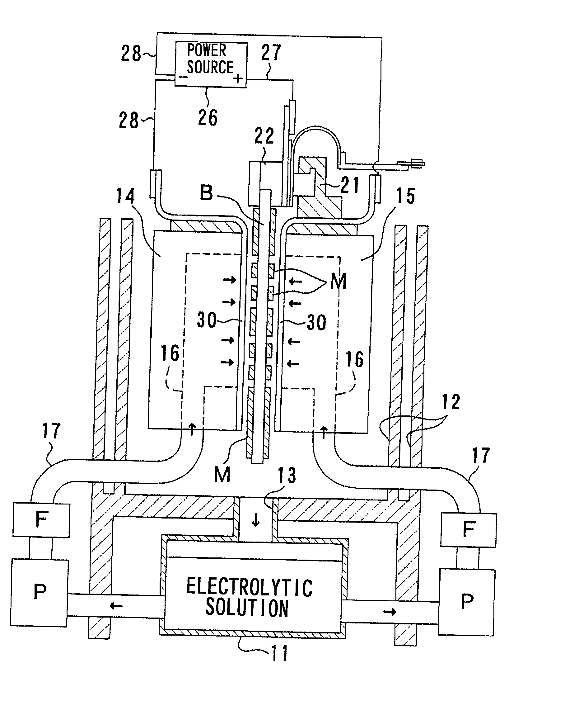
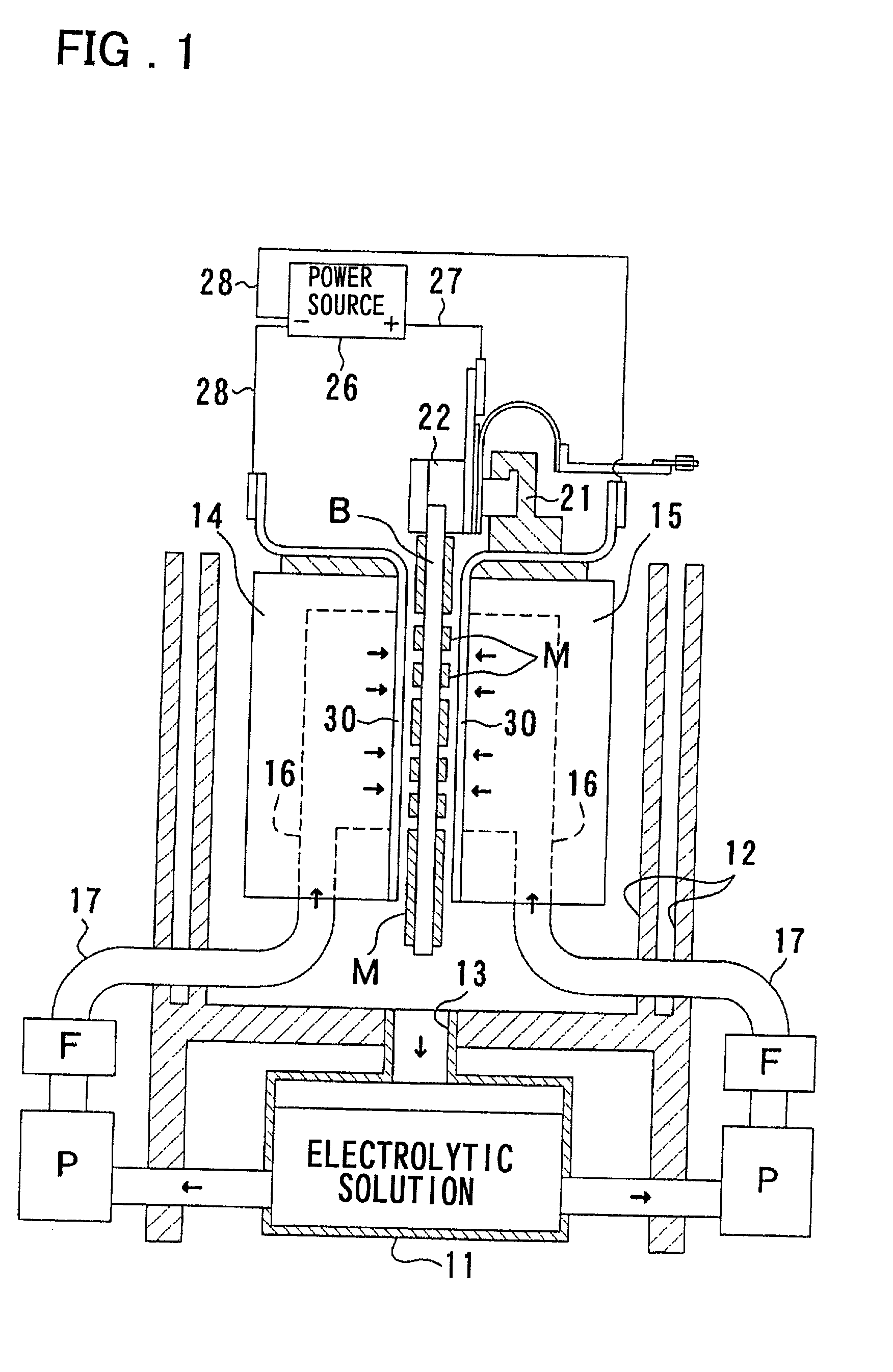
[0020] As shown in FIG. 1, an electrolytic solution storage tank 11 is placed at the lower part of an equipment for producing a separator of fuel cells. An air- or water-cooled temperature controller (not illustrated) is attached to this storage tank 11, and thereby, an electrolytic solution stored in the storage tank 11 is maintained almost at a desired temperature. A recovery tank 12 of two-tank system for recovering the electrolytic solution scattering during the feed of an electrolytic solution by injection is placed over the storage tank 11. A vertical communication passage 13 is provided in the center on the bottom wall of the recovery tank 12. An electrolytic solution is restored from the recovery tank 12 to the storage tank 11 through the vertical communication passage. Here, the recover...


PUM

PropertyMeasurementUnit
Shapeaaaaaaaaaa

Abstract

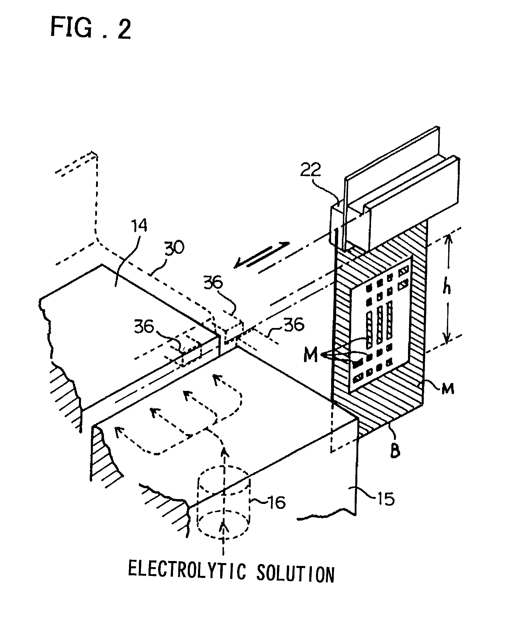
To provide a method capable of producing a separator integrated with a gas flow channel of fuel cells efficiently at low costs without deteriorating processing accuracy and the like. A plane-facing electrode nozzle 30 is placed oppositely to the face to be processed, which is partially covered with a mask M, of base material B of a separator. Under the condition of feeding electricity to the electrode nozzle 30 and the base material B of a separator, an electrolytic solution is injected and fed from the side of the electrode nozzle 30 to the face to be processed of the base material B from a direction that is almost perpendicular to the face. Thereby, the unmasked portion undergoes electrolytic etching with the electrolytic solution lying between the face to be processed and the electrode nozzle 30 to form recessed portions for making a gas flow channel.

Description

[0001] This invention relates to a method and equipment for producing a gas separator of fuel cells, which is integrated with a gas flow channel.[0002] Fuel cells generating electric power in response to the feed of fuel gas are generally manufactured by integrating plural electric cells. A separator lies between adjacent cells for the separation of both of them and additionally takes a role of material for forming a gas flow channel through which fuel gas is fed to the respective cells. With regard to techniques for forming a recessed portion (groove or depression) changing into a gas flow channel in a separator integrated with a gas flow channel like this, cutting method for machine cutting a metal plate changing into a base material of a separator to form grooves and the like, press working method for subjecting a metal plate changing into a base material of a separator to press working to form grooves and the like by stamping, and etching method for subjecting a metal plate chan...

Claims


Application Information

Patent Timeline
IPC IPC(8): B05C11/11B05D1/32B05D5/00B05D5/12B23H9/00H01M2/14C25D5/02C25D5/08C25D17/00C25F3/00C25F3/02C25F7/00H01M8/02
CPCH01M8/0206Y02E60/50H01M8/0258H01M8/0228Y02P70/50
Inventor MATSUKAWA, MASANORIKIMATA, RYUTAKUWABARA, YOUHEIDEWAKI, KENJIDEWAKI, SHINJI
Owner AISIN TAKAOKA CO LTD
Learn More