Modular lighting device and actuation system

a technology of module lighting and actuation system, which is applied in the direction of instruments, traffic signals, roads, etc., can solve the problems of not being able to generate, receive, store or send information, and achieve the effect of reducing resistan

Inactive Publication Date: 2002-07-04
ACOLYTE SYST +1
View PDF0 Cites 31 Cited by
  • Summary
  • Abstract
  • Description
  • Claims
  • Application Information

AI Technical Summary

Benefits of technology

0038] According to a preferred embodiment of the present invention the illumination device discloses a sensing means, programmable chip means, lighting means and power source in operative communication with one another. Switch means 32, which may be a sensor, will detect the presence of any number of triggers to effect an "on" or "off" condition of lighting means 26. The trigger that actuates the sensing means to an "on" or "off" condition may be light, radio frequency, movement, sound, magnetic fields or any other detectable change in physical state. For example, a light sensitive sensing means actuates device 100 to an "on" or "off" condition according to the level of ambient illumination and / or the alteration of visible and non-visible light frequencies. Photo-resistors, photodiodes, phototransistors, and photosensitive semiconductors may be used as light-sensitive resistors whose resistance decreases with the amount of light falling on them yielding alternate photo-sensors. Photo-sensors use light to control current passing through them and act as variable resistors controlled by the amount of light. They are photoconductive in that their resistance decreases in proportion to the amount of light that shines on them.
0039] Other sensing means or sensors may react to different external stimuli. In another preferred embodiment, for example, a motion detection sensor is adapted to detect and process any movement within a spatially-determined zone. A sound actuated sensing means may also be used, said sensor to react to sound, while radio frequency detectors react to specific radio frequencies. As a standard precept, all of the aforementioned sensors may be programmed to accept outside information relating to programmed parameters to trigger an effect and / or an "on" or "off" condition. In addition, level and proximity sensors may be operatively employed so that changes in physical tilt or intrusion will actuate device 100.

Problems solved by technology

Generally, prior art illumination devices respond to pressure on a mechanical on / off switch and are not capable of generating, receiving, storing or sending information.

Method used


Image

  • Modular lighting device and actuation system
  • Modular lighting device and actuation system
  • Modular lighting device and actuation system

Examples


Embodiment Construction

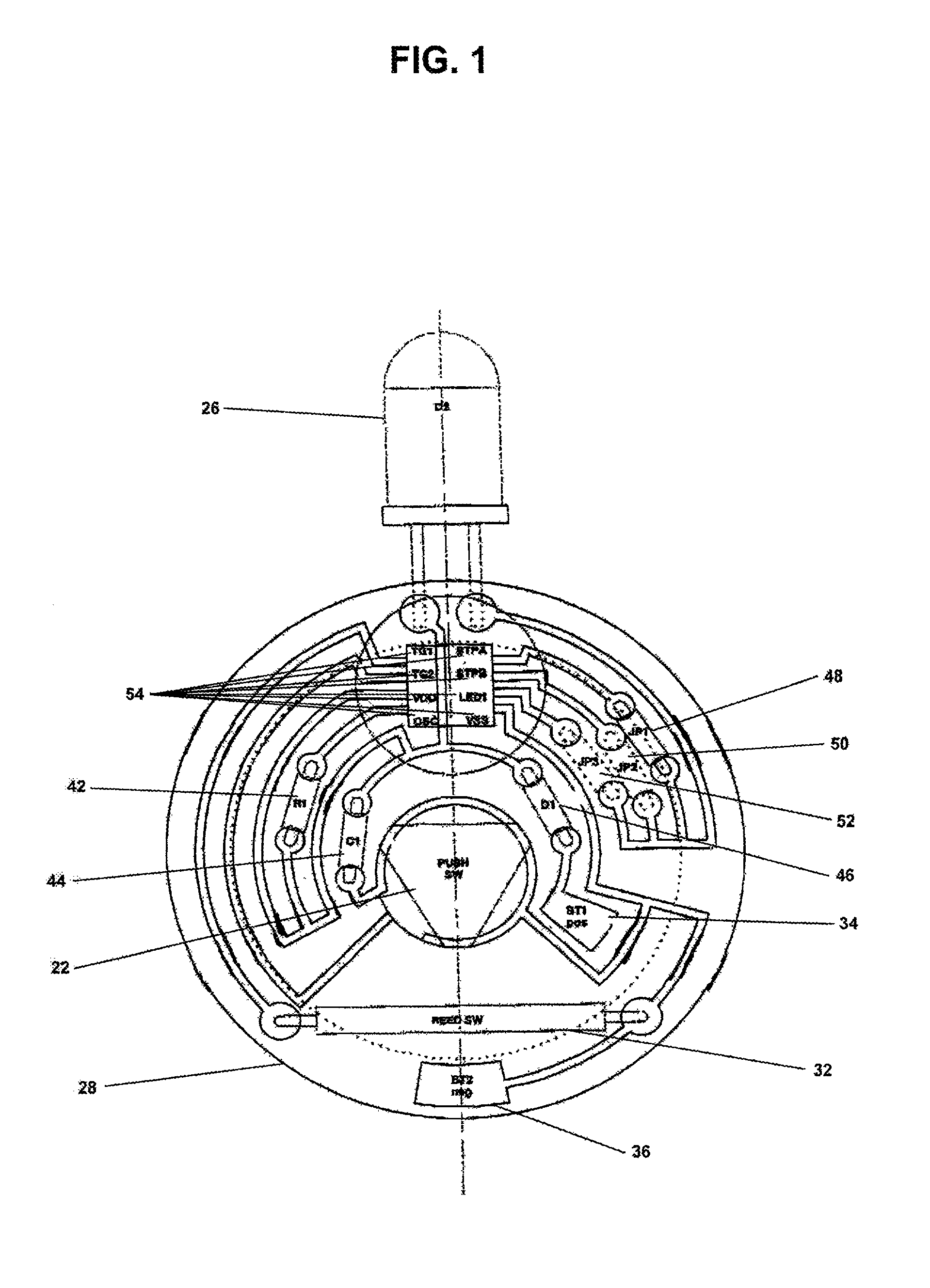
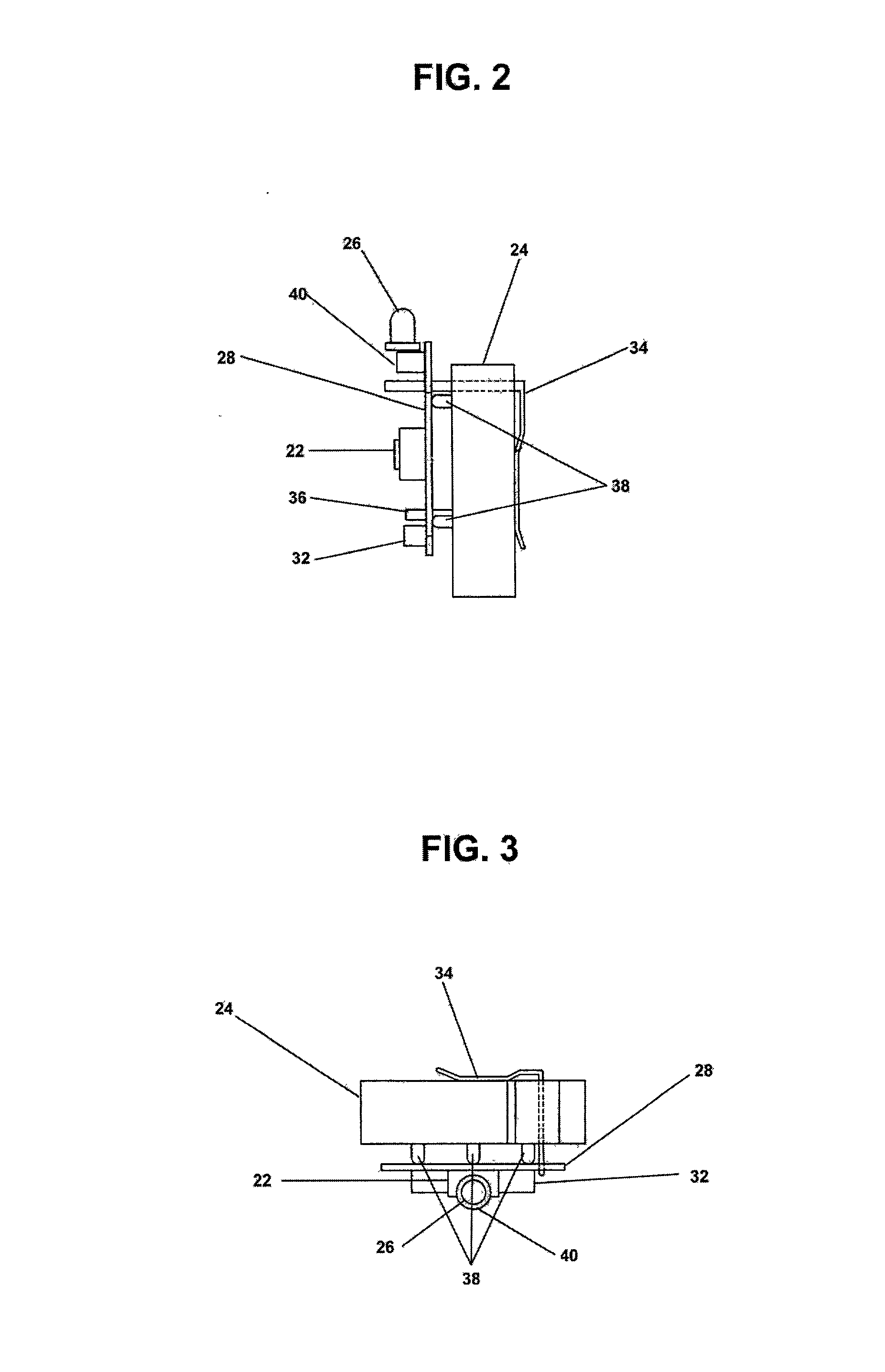
[0063] Set out below is a preferred series of parts for the device:

[0064] 1. A printed Circuit Board.

[0065] 2. ADPCM voice synthesizer type W528S03 speech chip.

[0066] 3. A 0.01 .mu.fd capacitor.

[0067] 4. Meder Reed Switch Part. No. MK15-B-2.

[0068] 5. MPD Battery Holder BH 1000-G-ND.

[0069] 6. CR-3032 Battery.

[0070] 7. E-switch Push Button TL3301N26OQG.

[0071] 8. 3 mm multidirectional light commercially produced by Hiyoshi Electric Co., Ltd.

[0072] 9. 3 jumpers.

[0073] 10. A low power diode IN914.

[0074] 11. A 1.2 Meg Ohms resistor which establishes 3 Mhz clock speed on speech chip.

[0075] These and other objects, advantages, features and aspects of the present invention will become apparent as the following description proceeds. While the foregoing embodiments of the invention have been set forth in considerable detail for the purposes of making a complete disclosure of the invention, it will be apparent to those of skill in the art that numerous changes may be made in such details withou...


PUM


Abstract

An illumination device that is highly durable, wireless, programmable, inexpensive emits little to no heat, is shockproof, water-resistant, energy efficient, is multidirectional, responds to a multitude of stimulus and adapts for a multitude of purposes. The programmable device provides varying amounts of light in accordance with programmed instructions.

Description

[0001] The instant invention relates generally to lighting devices and more specifically to a small, modular, digital, solid-state lighting device and actuation systems.[0002] Since the age of candles and oil lamps numerous advances have been made in the area of portable illumination devices. By the late 19.sup.th century, flashlights utilizing simple circuitry represented the next generation of illumination devices. Since the invention of flashlights, they have generally utilized a filament light bulb, an on / off switch and battery connected in an operative series. Such flashlights are generally well known within the art and for almost a century flashlight technology has generally remained unchanged.[0003] There are a number of flashlights on the market that are well known in the art. Included in these are two AAA-cell powered Lights (Pen Light and Mini-Pocket Light), the MiniMityLite, Mitylite, the photon light and Super Mitylite. While these lights vary according to the design and...

Claims


Application Information

Patent Timeline
Patent Type & Authority Applications(United States)
IPC IPC(8): H05B37/02
CPCH05B37/0209H05B47/17H05B47/165
Inventor GUERRIERI, SALVATOREADELMAN, LAWRENCE DAVID
Owner ACOLYTE SYST
Why Eureka
Try Eureka