System and method providing output signal control for a power supply

a technology of power supply and output signal, which is applied in the direction of process and machine control, emergency power supply arrangement, instruments, etc., can solve the problems of significant voltage drop across the junction, inability to enable current to flow from the common bus, and significant heat generated within the diode. significant and detrimental to the surrounding circui

Inactive Publication Date: 2002-09-12
MURATA POWER SOLUTIONS
View PDF0 Cites 35 Cited by
  • Summary
  • Abstract
  • Description
  • Claims
  • Application Information

AI Technical Summary

Benefits of technology

0018] In a third aspect, a method for selectively isolating a power supply from a common bus is provided. The method comprises determining direction and magnitude of current flowing between an output path of the power supply and the common bus, increasing a resistance value of a resistive element located between the output path and the common bus as the current flows from the output path and as the current decreases and decreasing the resistance value as the current flows from the output path and as the current increases.

Problems solved by technology

Accordingly, if the local power supply fails, the blocking action of the diode ensures that the failure does not enable current to flow from the common bus into the circuitry of the failed local power supply.
When a diode is forward biased, there is a significant voltage drop across its junction.
When output current is in the range of tens to hundreds of amperes ("amps"), heat generated within a diode can be significant and detrimental to surrounding circuits.
Though the use of diodes increase system fault tolerance and reliability, the heat associated with them has a negative effect on system MTBF (mean time between failure).
However, by using a FET which operates only in either its cut-off region or its saturated region, it is difficult to detect and react to a fault condition present between the power supply and the common bus.
It may be difficult to detect the fault condition using current values and voltage values in that range.
Further, obtaining a larger voltage signal using a FET having a higher R.sub.ds-on or a fixed sensing resistor generates more heat under high load conditions.

Method used


Image

  • System and method providing output signal control for a power supply
  • System and method providing output signal control for a power supply
  • System and method providing output signal control for a power supply

Examples


first embodiment

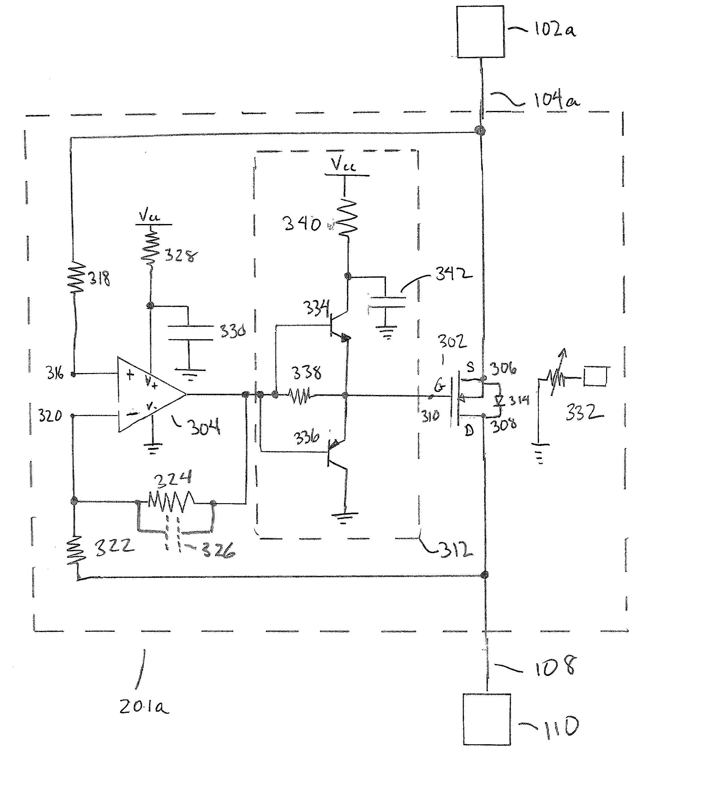
[0039] Referring to FIG. 4, elements of circuit 201a (circuit 201) are shown in detail. The main components of circuit 201a are resistive element 302 (corresponding to element 202) and control element 304 (corresponding to element 204). Resistive element 302 is connected to output 104a and common bus 108. Resistive element provides a variable resistance between nodes 104a and 108. Control element 304 controls the resistance shown by resistive element 302 to circuit 201a by providing an appropriate control signal to resistance element 302. Accordingly, control element 304 can cause reverse current flow to be impeded from flowing into the power supply 102 by setting the resistance value to be extremely high.

[0040] In the first embodiment, resistive element 302 is an N-channel MOSFET ("FET") such as STV160NF02L available from STMicroelectronics of Phoenix, Ariz. Input terminal 306 is the source of the FET 302; output terminal 308 is the drain of the FET 302 and control terminal 310 is ...

second embodiment

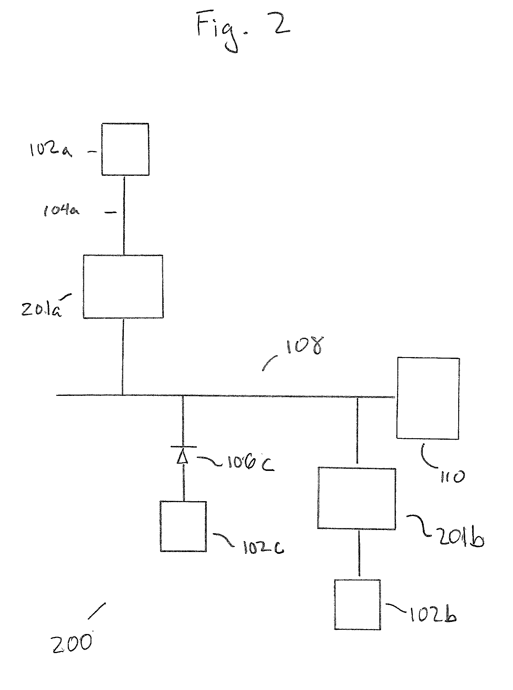
[0070] Referring to FIGS. 2 and 7, the following is a description of control circuit 201b of control circuit 201. Control circuit 201b senses voltages about a resistive element at node 104b and at node 108, digitizes the voltages, calculates required difference and gain functions in the digital domain (including any expansion / compression / frequency dependencies or offsets), and converts the digital output to an appropriate analog signal. The analog signal is provided to control terminal 610 of the resistive element 602 (corresponding to element 202 of FIG. 3).

[0071] Referring to FIG. 7, modules 601 and 605 are analog to digital converters that digitize voltages at nodes 104b and 108, respectively. Module 604 (corresponding to element 204 of FIG. 3) performs digital domain processing of digitized samples of the voltages and may be a microcontroller, a microprocessor, or a device controlled by separate microprocessor 606.

[0072] Module 603 is a digital to analog converter, which transla...


PUM


Abstract

A control system for selectively isolating a power supply from a common bus is provided. The control system comprises a connection to an output path of an output signal of the power supply and a resistive element providing a variable resistance between an input terminal and an output terminal. The input terminal is connected to the connection and the output terminal is connected to the common bus. The resistive element further comprises a control terminal allowing adjustment of the variable resistance. A control element provides a control signal to the control terminal; the control element is responsive to current flowing between the output path and the common bus.

Description

[0001] The invention relates generally to control circuitry for a power supply, in particular reverse current control circuits for a power supply.[0002] A fault tolerant redundant power system comprises a plurality of local power supplies which individually provide their outputs to a common bus. The power signal on the common bus is provided to a device, which appears as an electrical load.[0003] To make the power system fault tolerant, isolation circuitry is often provided at each local power supply which isolates it from the rest of the system in the event of its failure.[0004] Often, the isolation circuitry comprises an OR-ing or blocking diode which connects the output of the local power supply to the common bus. A forward biased blocking diode enables current to flow from the local power supply to the common bus, but blocks reverse current flow therethrough. Accordingly, if the local power supply fails, the blocking action of the diode ensures that the failure does not enable c...

Claims


Application Information

Patent Timeline
Patent Type & Authority Applications(United States)
IPC IPC(8): H02J1/10
CPCH02J1/108Y10T307/615Y10T307/696Y10T307/544H02J1/001
Inventor BUCHANAN, MARLOWE JAMES
Owner MURATA POWER SOLUTIONS
Why Eureka
Try Eureka