Method for high resolution magnetic resonance analysis using magic angle technique

a magnetic resonance analysis and magic angle technology, applied in the field of magnetic resonance analysis, can solve the problems of net nuclear magnetization, population imbalance between energy levels, broadening of the nmr resonance line, etc., and achieve the effect of increasing the resolution of nmr spectra, and increasing the sensitivity of nmr spectra

Inactive Publication Date: 2002-09-12
BATTELLE MEMORIAL INST
View PDF0 Cites 14 Cited by
  • Summary
  • Abstract
  • Description
  • Claims
  • Application Information

AI Technical Summary

Benefits of technology

[0019] Described herein are methods for magnetic resonance analysis of an object by combining slow magic angle spinning techniques with certain radio frequency pulse sequences. This combination provides for the first time a method for obtaining high resolution spectra of a biological object that (a) does not damage tissue or cellular structure in the biological object and (b) substantially eliminates spinning sideband peaks in the spectra associated with slow magic angle spinning. Contrary to the conventional expectation that the diffusion of the molecules containing the nuclei of interest in the internal static local magnetic fields would be problematic for slow spinning, the inventors have surprisingly discovered that the presently disclosed methods provide NMR spectra with a resolution comparable to or better than the spectral resolution obtained with conventional fast MAS, and that are substantially free of spinning sidebands peaks at low rotation frequencies.
[0029] For in vitro investigations of small objects, the methods that include a 2D-PASS segment are especially useful for increasing the NMR sensitivity in a MRI experiment, and for increasing the sensitivity and resolution of NMR spectra of .sup.1H and other NMR-sensitive nuclei in MRS experiments in cells and intact excised tissues and organs. For in vivo investigations of larger biological objects, the methods that include a PHORMAT segment are especially useful for increasing the resolution of NMR spectra of .sup.1H and other NMR-sensitive nuclei in MRS experiments in live animals and humans. The slower rotating of the sample minimizes, if not substantially eliminates tissue and cellular damage. The presently disclosed methods have several important advantages over fast MAS: (I) larger rotors and, henceforth, larger samples can be used, which increases the NMR sensitivity (especially important when the method is applied for less NMR-sensitive nuclei than protons); (II) the structural integrity of the biological sample undergoes minimal or no changes under slow spinning (i.e., artifacts in the spectra induced by the fast spinning, which are a result of the sample deformation during the spinning, are avoided); and (III) besides the isotropic spectrum, the anisotropy patterns of the individual water and metabolite lines can be determined (allowing one to obtain information regarding the immediate surroundings of the various compounds).

Problems solved by technology

This results in a population imbalance between the energy levels and a net nuclear magnetization.
These fields cause slight variations in the resonance frequency of the individual nuclei, which results in a broadening of the NMR resonance line.
However, a serious problem associated with these applications is the relatively large widths of the MR resonance lines that are observed using conventional MRI and MRS.
This reduces the MRI and MRS sensitivity, and, for MRS, can result in severely overlapping spectral lines, which seriously hampers the analysis of the spectrum.
Using cell extracts can eliminate this broadening, but this procedure cannot be applied in live subjects, it is time consuming and may introduce spectral artifacts.
A problem with MAS is that when the value of the spinning rate is small compared to the width of the broadening, the resonant peak splits into a group of spinning sidebands (SSBS) separated by the spinning rate.
If the value of the spinning rate is less than the isotropic spectral width, the analysis of the spectra becomes considerably difficult due to the overlapping of the SSBs associated with the different resonant peaks.
However, the large centrifugal force associated with such high spinning rates destroys the tissue structure and even part of the cells (see Weybright et al.).
Consequently, MAS at a high spinning speed is not suitable, for example, to map the metabolite distribution in intact biological tissues or to study live cells, and is impossible to use on live subjects.
This effect worsens if the spinning frequency is reduced, resulting in imperfect suppression of the SSB's.
In other words, it was expected that MAT techniques could not be employed in biological materials because the Brownian motions, which cause metabolites to diffuse throughout the cells, would make it impossible to remove the susceptibility broadening with slow MAS.
Indeed, it was shown that in a standard fast MAS experiment of water embedded in glass beads the spectral lines become broad even at spinning speeds of several hundred Hz (see Leu et al, Amplitude Modulation and Relaxation Due to Diffusion in NMR Experiments With a Rotating Sample, Chem Phys Lett 2000; 332:344-350), and that a sideband-suppression technique called total suppression of sidebands (TOSS) was ineffective for suppressing SSB's arising from water embedded in glass beads when the spinning speed was lowered to 1 kHz (see Liu et al, Manipulation of Phase and Amplitude Modulation of Spin magnetization in Magic Angle Spinning NMR in the Presence of Molecular Diffusion, J. Chem. Phys. 2001: 114: 5729-5734).
However, this approach was never considered any further.

Method used


Image

  • Method for high resolution magnetic resonance analysis using magic angle technique
  • Method for high resolution magnetic resonance analysis using magic angle technique
  • Method for high resolution magnetic resonance analysis using magic angle technique

Examples


fifth embodiment

[0063] An example of a magnet configuration for electronically rotating the magnetic field while the biological object is held stationary per the above-described fifth embodiment is shown in FIG. 12. A complementary pair of first RF coils 21 are arranged to generate an alternating magnetic field B.sub.x in the x-direction, given by B.sub.x={square root}2 / 3.multidot.B.sub.0.multidot.sin(.omega..sub.rt). A complementary pair of second RF coils 22 are arranged to generate a static magnetic field B.sub.y in the y-direction, given by B.sub.y=B.sub.0 / {square root}3. A complementary pair of third RF coils 23 are arranged to generate an alternating magnetic field B.sub.z={square root}2 / 3.multidot.B.sub.0.multidot.cos(.omega..sub.rt). DC and AC currents passing through each set of coils 21, 22, 23 produce three mutually orthogonal magnetic field components. A biological object 20 is placed in the center of the coil system. As a result, the overall magnetic field is given by B.sub.0, which ro...

sixth embodiment

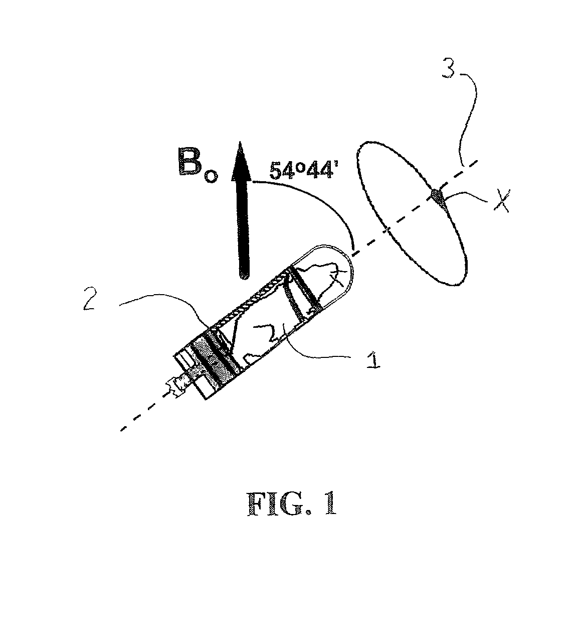
[0064] An example of a configuration for physically rotating the magnet while the biological object is held stationary per the above-described sixth embodiment is shown in FIG. 13. A magnet bore 10 defines a void 11 for receiving a biological object (e.g., a human) 12 and a longitudinal axis 13. The longitudinal axis 13 of the magnet bore 10 is aligned at the magic angle of 54.degree.44' relative to the direction of the main magnetic field B.sub.0. The main magnetic field B.sub.0 is generated by the magnet bore 10. The magnet bore 10 may be rotated mechanically around the longitudinal axis 13 as shown by the directional arrow in FIG. 13.

seventh embodiment

[0065] The above-described seventh embodiment involves rotating both the biological object and the main magnetic field in respectively opposite rotational directions. For example, the device depicted in FIG. 12 or FIG. 13 could be modified so that the biological object also rotates. Such rotation allows for the rotational frequency of both the biological object and the main magnetic field to decrease by a factor of two.

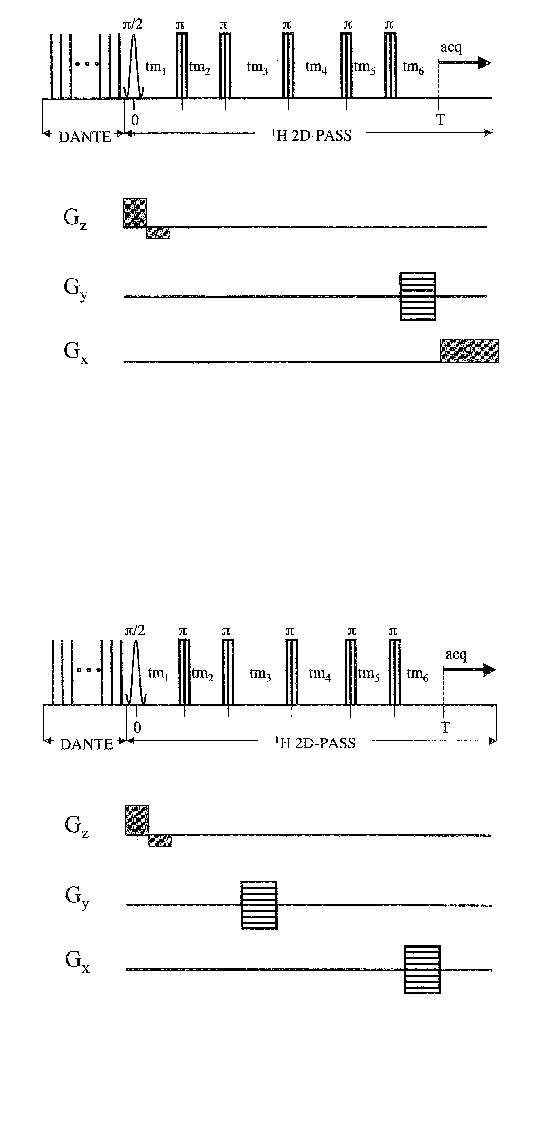
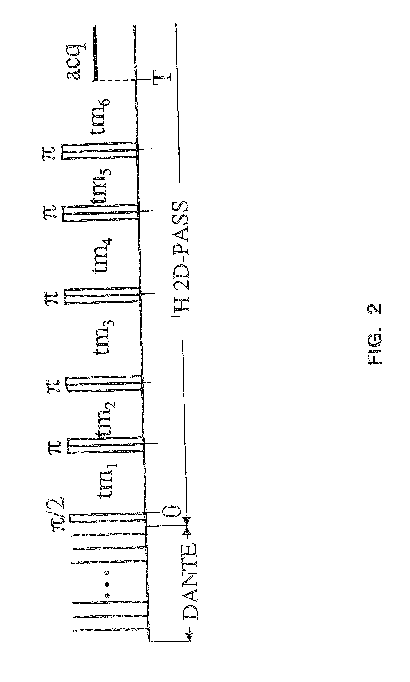
[0066] The RF pulse sequence employed in the presently disclosed methods may be any sequence or series of sequences capable of producing a high-resolution spectrum in a slow MAS approach that is substantially free of spinning sidebands. The RF pulse sequences can be repeated during every rotor period (i.e., one 360.degree. rotation of the object) throughout the duration of the scanning. A typical characteristic of these RF pulse sequences may be isotropic-anisotropic chemical shift correlation pulse sequences. Exemplary RF pulse sequences include MAT sequences. These ...


PUM

PropertyMeasurementUnit
rotational frequencyaaaaaaaaaa
magic angleaaaaaaaaaa

Abstract

A method of performing a magnetic resonance analysis of a biological object that includes placing the object in a main magnetic field (that has a static field direction) and in a radio frequency field; rotating the object at a frequency of less than about 100 Hz around an axis positioned at an angle of about 54.degree.44' relative to the main magnetic static field direction; pulsing the radio frequency to provide a sequence that includes a phase-corrected magic angle turning pulse segment; and collecting data generated by the pulsed radio frequency. The object may be reoriented about the magic angle axis between three predetermined positions that are related to each other by 120.degree.. The main magnetic field may be rotated mechanically or electronically. Methods for magnetic resonance imaging of the object are also described.

Description

PRIORITY CLAIM[0001] This application is a continuation-in-part of U.S. application Ser. No. 09 / 803,381, filed Mar. 9, 2001, incorporated herein by reference.FIELD[0003] The present disclosure relates to magnetic resonance (MR) analysis, particularly to magnetic resonance spectroscopy (MRS) and imaging (MRI) of biological objects.BACKGROUND[0004] Magnetic resonance is a phenomenon exhibited by a select group of atomic nuclei and is based upon the existence of nuclear magnetic moments in these nuclei (termed "gyromagnetic" nuclei). When a gyromagnetic nucleus is placed in a strong, uniform and steady magnetic field (a so-called "external field" and referred to herein as a "static" magnetic field), it precesses at a natural frequency known as a Larmor frequency. The Larmor frequency is characteristic of each nuclear type and is dependent on the applied field strength in the location of the nucleus. Typical gyromagnetic nuclei include .sup.1H (protons), .sup.13C, .sup.19F and .sup.13P....

Claims


Application Information

Patent Timeline
Patent Type & Authority Applications(United States)
IPC IPC(8): G01R33/20G01N24/08G01N33/483G01R33/30G01R33/465G01R33/54
CPCG01R33/307G01R33/54
Inventor WIND, ROBERT A.HU, JIAN ZHI
Owner BATTELLE MEMORIAL INST
Why Eureka
Try Eureka