Optical wavelength division multiplex signal monitoring apparatus

a signal monitoring and optical wavelength technology, applied in multiplex communication, transmission monitoring, instruments, etc., can solve the problems of not being applicable to multi-wavelength optical signals, unable to directly reflect bit error rates, and inability to detect waveform degradation, so as to increase the range of optical signal bit rate, simplify the entire configuration, and widen the effect of bandwidth

Active Publication Date: 2002-09-12
NIPPON TELEGRAPH & TELEPHONE CORP
View PDF8 Cites 22 Cited by
  • Summary
  • Abstract
  • Description
  • Claims
  • Application Information

AI Technical Summary

Benefits of technology

0043] Furthermore, when nonlinear optical mediums are used in the present invention, it is not necessary for each of the nonlinear optical mediums to have a wide bandwidth because it can only handle the wavelength of the incident optical signal. In addition, although the nonlinear optical mediums as a whole must be applicable to all the optical signal wavelengths (wide...

Problems solved by technology

Although the conventional technique 2 can obtain the optical signal-to-noise ratio, it has a problem in that it cannot detect the waveform degradation due to the wavelength dispersion in an optical fiber, or the transmission degradation due to the waveform degradation by the polarization dispersion, and that it cannot reflect the bit error rate directly.
Although they can respond to an increase i...

Method used


Image

  • Optical wavelength division multiplex signal monitoring apparatus
  • Optical wavelength division multiplex signal monitoring apparatus
  • Optical wavelength division multiplex signal monitoring apparatus

Examples


first embodiment

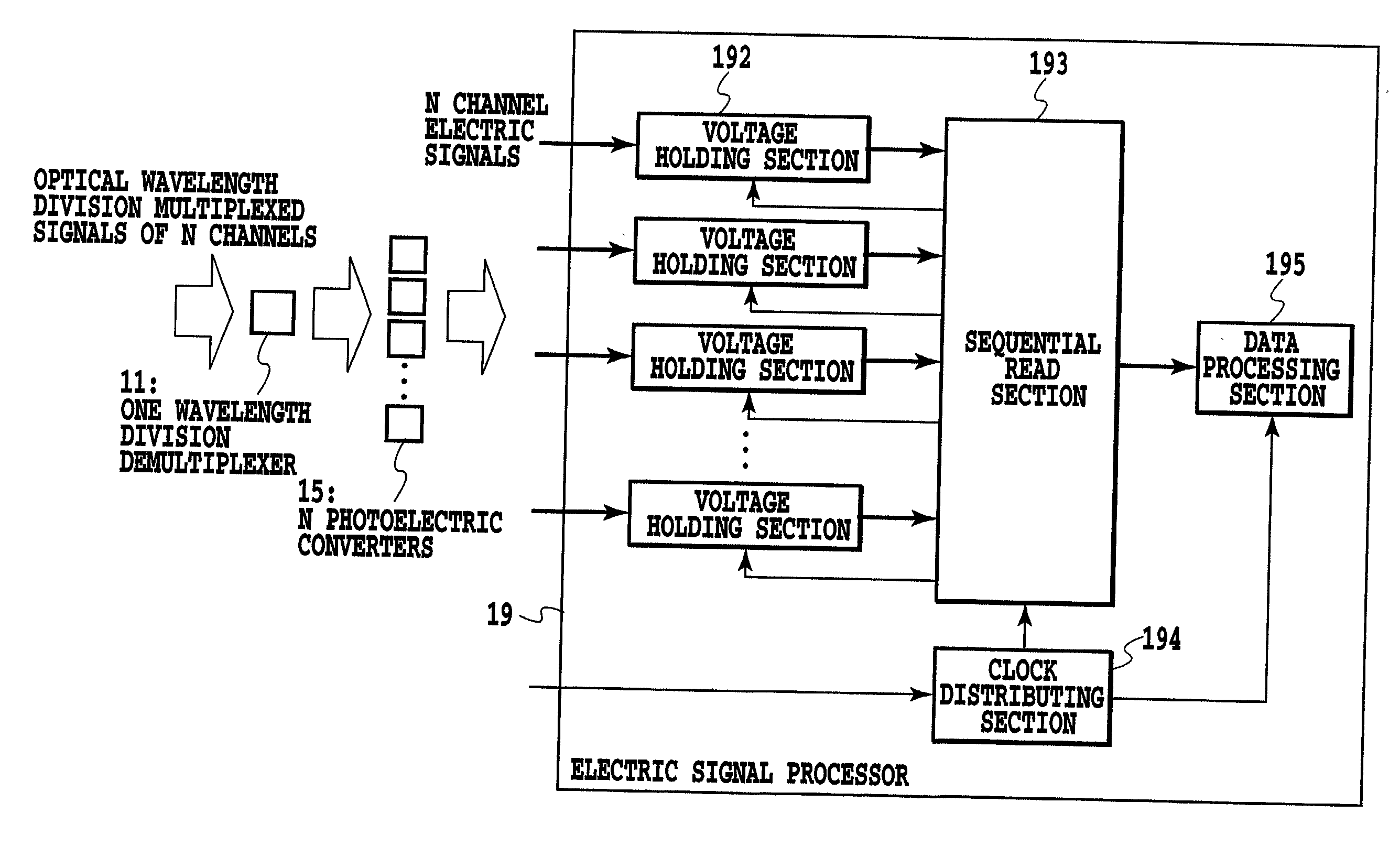
[0104] FIG. 7 shows a configuration of an optical wavelength division multiplexed signal monitoring apparatus of a first embodiment in accordance with the present invention. A wavelength division demultiplexer 11 carries out the wavelength division demultiplexing of an optical wavelength division multiplexed signal consisting of N optical signals with a bit rate f.sub.0 (bits / s) that undergo the wavelength multiplexing. Subsequently, N photoelectric converters 15 convert them into N channel electric signals to be supplied to an electric signal processor 19. As will be described later, the present embodiment is an example in which the electric signal processor 19 stores the N channel electric signals for a predetermined time period, and processes them by reading them sequentially, thereby reducing the electric signal processing process to a single system.

[0105] The electric signal processor 19 comprises N input ports for accepting the N channel electric signals and N voltage holding ...

second embodiment

[0106] FIG. 8 shows a configuration of an optical wavelength division multiplexed signal monitoring apparatus of a second embodiment in accordance with the present invention. The wavelength division demultiplexer 11 carries out the wavelength division demultiplexing of the optical wavelength division multiplexed signal consisting of N optical signals with a bit rate f.sub.0 (bits / s) that undergo the wavelength multiplexing. Subsequently, the N photoelectric converters 15 convert them into N channel electric signals to be supplied to an electric signal processor 19. As will be described later, the present embodiment is an example in which a switching section 191 in the electric signal processor 19 sequentially switches connection of the N channel analog electric signals, thereby reducing the electric signal processing process to a single system.

[0107] The electric signal processor 19 comprises N input ports for accepting the N channel electric signals and the single switching section...

third embodiment

[0108] FIG. 9 shows a configuration of an optical wavelength division multiplexed signal monitoring apparatus of a third embodiment in accordance with the present invention. A wavelength selecting section 42 selects one of N optical signals with a bit rate f.sub.0 (bits / s) that are wavelength multiplexed into the optical wavelength division multiplexed signal, and the selected optical signal reaches the electric signal processor 19 as a single-channel electric signal through the single photoelectric converter 15.

[0109] The electric signal processor 19 comprises one input port for accepting the one-channel electric signal, a voltage holding section 192, a clock distributing section 194 and a data processing section 195. The voltage holding section 192 carries out the analog-to-digital conversion of the input electric signal, holds the digital signal voltage for a time period, and outputs it in response to the external trigger signal delivered by the clock distributing section 194. Th...


PUM


Abstract

An optical signal quality degradation monitoring apparatus for monitoring an optical wavelength division multiplex signal is implemented in a small size. To monitor the optical signal quality degradation in the optical wavelength division multiplex signal by a configuration as simple as possible, the following configurations are used: A configuration using an optical wavelength division demultiplexer and a sampling clock generator to make one an electric signal processor; A configuration using an optical sampling pulse train generator, an optical multiplexer, a nonlinear optical medium, and an optical wavelength division demultiplexer to make one an electric signal processor; or a configuration using a selection wavelength control section, an optical wavelength selecting section, and a sampling clock generator to make one electric signal.

Description

[0001] This application is based on Japanese Patent Application Nos. 2001-064042 filed Mar, 7, 2001, and 2001-342257 filed Nov. 7, 2001, the contents of which are incorporated hereinto by reference.BACKGROUND OF THE INVENTION[0002] 1. Field of the Invention[0003] The present invention relates to an optical wavelength division multiplexed signal monitoring apparatus.[0004] 2. Description of the Related Art[0005] Wavelength division multiplexing (WDM) is a technique that multiplexes a plurality of optical signal channels (called WDM channels from now on) with different carrier optical wavelengths into a single optical fiber and transmits them through the optical fiber. The technique is useful to deal with an increasing transmission capacity. The WDM technique includes the following as typical signal monitoring apparatuses.[0006] Conventional technique 1: It identifies a faulty section and obtains a switching start signal for each WDM channel by carrying out parity check called bit int...

Claims


Application Information

Patent Timeline
IPC IPC(8): H04B10/00H04B10/02H04B10/079H04B10/08H04J14/02H04L7/00
CPCH04B10/07953H04J14/02H04L7/0075
Inventor SHAKE, IPPEITAKARA, HIDEHIKO
Owner NIPPON TELEGRAPH & TELEPHONE CORP
Why Eureka
Try Eureka