Optical interleaving with enhanced spectral response and reduced polarization sensitivity

Inactive Publication Date: 2002-09-12
GAZILLION BITS
View PDF1 Cites 32 Cited by
  • Summary
  • Abstract
  • Description
  • Claims
  • Application Information

AI Technical Summary

Benefits of technology

0025] According to a preferred embodiment in which the optical interleaver is in a free-space configuration, the splitting element that receives the incident beam comprises a partially reflective surface positioned such that a normal to the reflective surface is at a less-than-30 degree angle with respect to the incoming beam. As this angle is reduced even further below 30 degrees, the optical interleaver becomes increasingly robust against polarizations in the incident light beam, because the splitting ratio of the reflective surface becomes increasingly stable as this angle is reduced. Angles of 10 degrees or less are even more preferable in providing an optical interleaver that is stable against polarizations in the incoming beam. Reducing the above splitting angle in accordance with the preferred embodiments will stabilize single-cavity optical interleavers as well as dual-cavity optical interleavers.
0026] In accordance with another preferred embodiment, thermal stability of the optical interleaver is enhanced. In particular, the first and second paths traversed by the respective split-beam portions wi

Problems solved by technology

However, known current electro-optical modulators are only capable of modulating light at a rate of about 10 GHz, corresponding to a wavelength spread of only about 0.16 nm.
As international standards continue to reduce DWDM channel spacings, conventional dichroic filters used in add/drop devices have not been able to keep up in terms of the narrowness of their passband, with the known best dichroic filters only achieving effective channel separation for channel spacings of about 100 GHz or greater.
The optical interleaver 300, however, contains several shortcomings which would limit its use as a practical interleaving device.
These values would lead to large amounts of crosstalk and signal distortion.
It has been found that even when unpolarized light is introduced into a fiber in a real-world optical fiber communication system, unwanted polarizations can arise due to many different factors, such as excessive twists or loops in the optical fiber.
Finally, the optical interleaver 300 is not thermally robu

Method used


Image

  • Optical interleaving with enhanced spectral response and reduced polarization sensitivity
  • Optical interleaving with enhanced spectral response and reduced polarization sensitivity
  • Optical interleaving with enhanced spectral response and reduced polarization sensitivity

Examples


Example

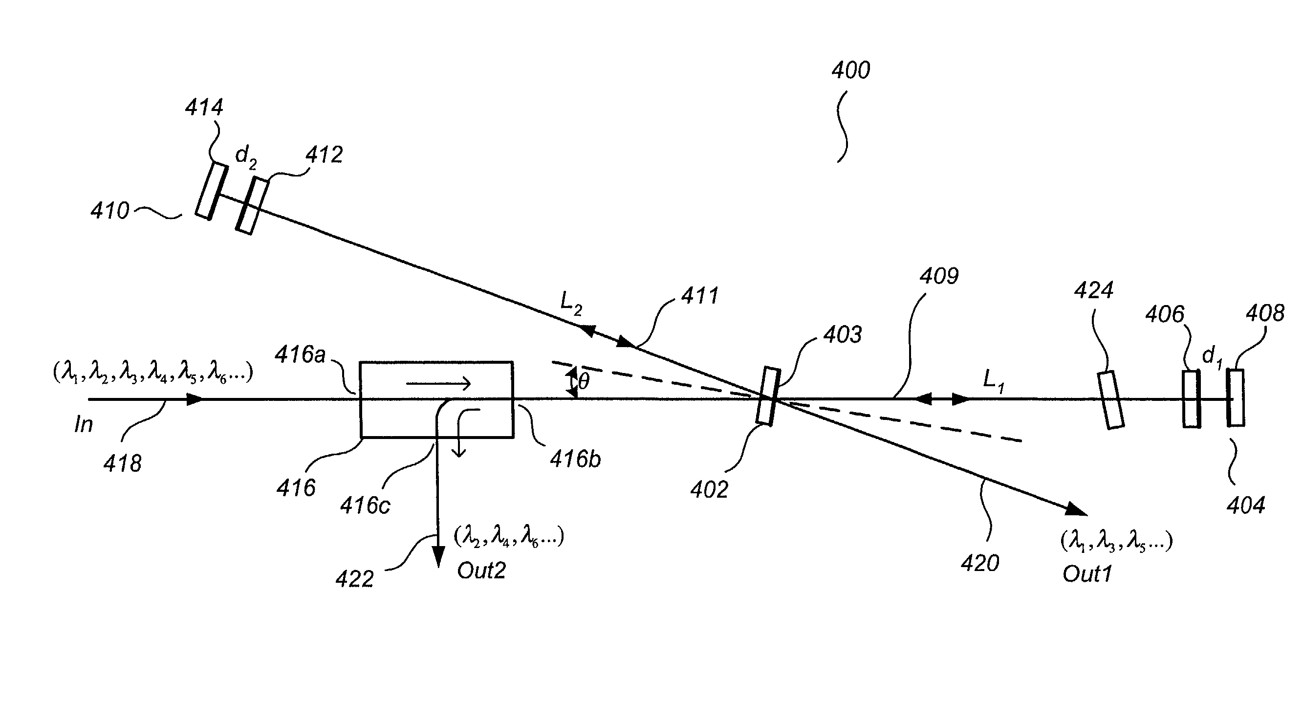
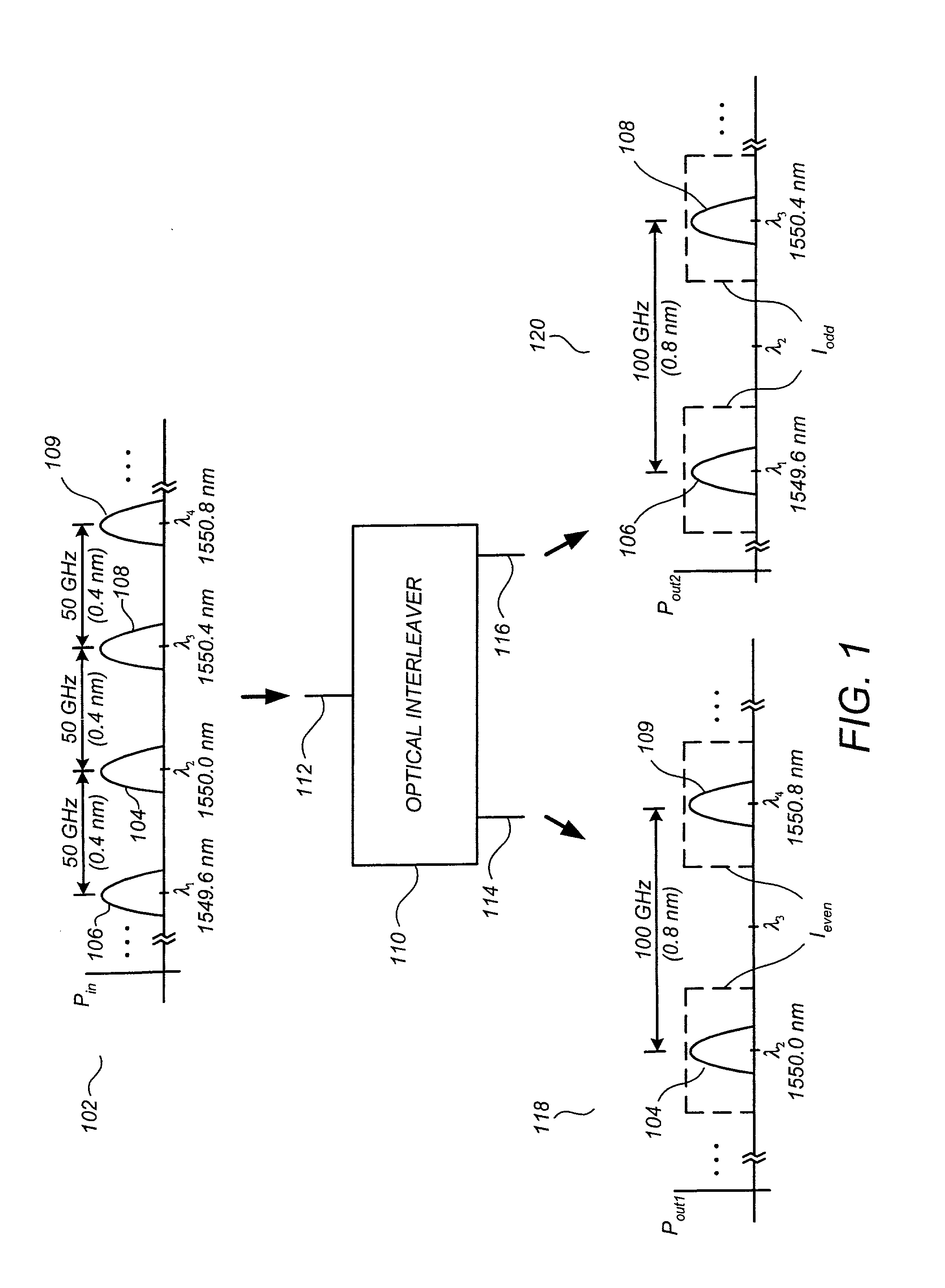
[0038] FIG. 4 illustrates an optical interleaver 400 in accordance with a preferred embodiment. Optical interleaver 400 comprises a beamsplitter 402 having a partially reflective surface 403, a first resonant cavity 404 having an inner mirror 406 and an outer mirror 408, a second resonant cavity 410 having an inner mirror 412 and an outer mirror 414, and a circulator 416 comprising a first port 416a, a second port 416b, and a third port 416c. At an input 418 coupled to first port 416a of circulator 416 is an incident beam containing a WDM signal comprising a plurality of channels at center wavelengths .lambda..sub.1, .lambda..sub.2, .lambda..sub.3, .lambda..sub.4, .lambda..sub.5, .lambda..sub.6, . . . which are usually, but not necessarily, equally spaced with a channel spacing .DELTA.f. By way of example and not by way of limitation, the channel spacing .DELTA.f may be 50 GHz, as exemplified by plot 102 of FIG. 1, supra. At a first output 420 coupled to partially reflective surface...


PUM


Abstract

An optical interleaver for receiving an incident beam carrying a wavelength-division-multiplexed (WDM) signal comprising a plurality of channels at center wavelengths .lambda..sub.1, .lambda..sub.2, .lambda..sub.3, .lambda..sub.4, .lambda..sub.5, .lambda..sub.6, . . . and generating therefrom at least one de-interleaved output signal comprising the odd channels .lambda..sub.1, .lambda..sub.3, .lambda..sub.5, . . . or the even channels .lambda..sub.2, .lambda..sub.4, .lambda..sub.6, . . . is described. The optical interleaver comprises a splitting element for splitting an incident beam into a first optical signal directed along a first path and a second optical signal directed along a second path, a first resonant element positioned along the first path, a second resonant element positioned along the second path, and a combining element positioned to receive and to interferometrically combine the outputs of the first and second resonant to produce the output signal. The optical interleaver may be implemented using a free-space configuration using a beamsplitter and a plurality of resonant cavities such as asymmetric Fabry-Perot resonators or Michelson-Gires-Tournois resonators. In an alternative preferred embodiment, the optical interleaver may be implemented in a Mach-Zender-style configuration using couplers and fiber ring resonators. According to a preferred embodiment in which the optical interleaver is in a free-space configuration, the splitting element that receives the incident beam comprises a partially reflective surface positioned such that a normal to the reflective surface is at a less-than-30 degree angle with respect to the incoming beam for increased stability against polarizations in the incoming beam. According to another preferred embodiment, thermal stability of the optical interleaver is enhanced by configuring and dimensioning the optical interleaver such that the amount of glass or other optical material in the first and second split-beam paths is equalized. In accordance with reciprocity principles, the optical interleaver is readily adapted to operate as an interleaver, de-interleaver, or add/drop multiplexer.

Description

FIELD[0001] This patent specification relates to fiber optic communication systems. More particularly, it relates to optical interleaving for combining and / or separating optical signals.BACKGROUND[0002] As the world's need for communication capacity continues to increase, the use of optical signals to transfer large amounts of information has become increasingly favored over other schemes such as those using twisted copper wires, coaxial cables, or microwave links. Optical communication systems use optical signals to carry information at high rates over an optical path such as an optical fiber. Optical fiber communication systems are generally immune to electromagnetic interference effects, unlike the other schemes listed above. Furthermore, the silica glass fibers used in fiber optic communication systems are lightweight, comparatively low cost, and are able to carry tens, hundreds, and even thousands of gigabits per second across large distances.[0003] Indeed, one 1998 experiment ...

Claims


Application Information

Patent Timeline
IPC IPC(8): H04J14/02
CPCG02B6/2934G02B6/29349G02B6/29353G02B6/29358G02B6/29386H04J14/02H04J14/0208H04J14/0213
Inventor JEONG, HWAN J.CHEN, XING
Owner GAZILLION BITS
Why Eureka
Try Eureka