Multi-functional composite structures

Inactive Publication Date: 2002-09-12
ADVANCED CERAMICS
View PDF0 Cites 32 Cited by
  • Summary
  • Abstract
  • Description
  • Claims
  • Application Information

AI Technical Summary

Benefits of technology

0011] The present invention overcomes the problems encountered in conventional systems and methods of manufacture by providing materials having properties that allow the materials to be used to perform multiple tasks while providing enhanced structural benefits within a particular system. The present invention also provides methods of fa

Problems solved by technology

These systems, however, contain many limitations and disadvantages due to the number and types of components required to perform the various tasks.
Use of these piezoelectric and/or electrostrictive ceramics is limited by certain disadvantages of the materials.
One significant disadvantage is that the ceramics tend to be brittle and weak.
Thus, tensile strength limitations are often a limiting factor in design systems utilizing these materials.
The poling process, however, is a challenging task that often results in elec

Method used


Image

  • Multi-functional composite structures
  • Multi-functional composite structures
  • Multi-functional composite structures

Examples


example 1

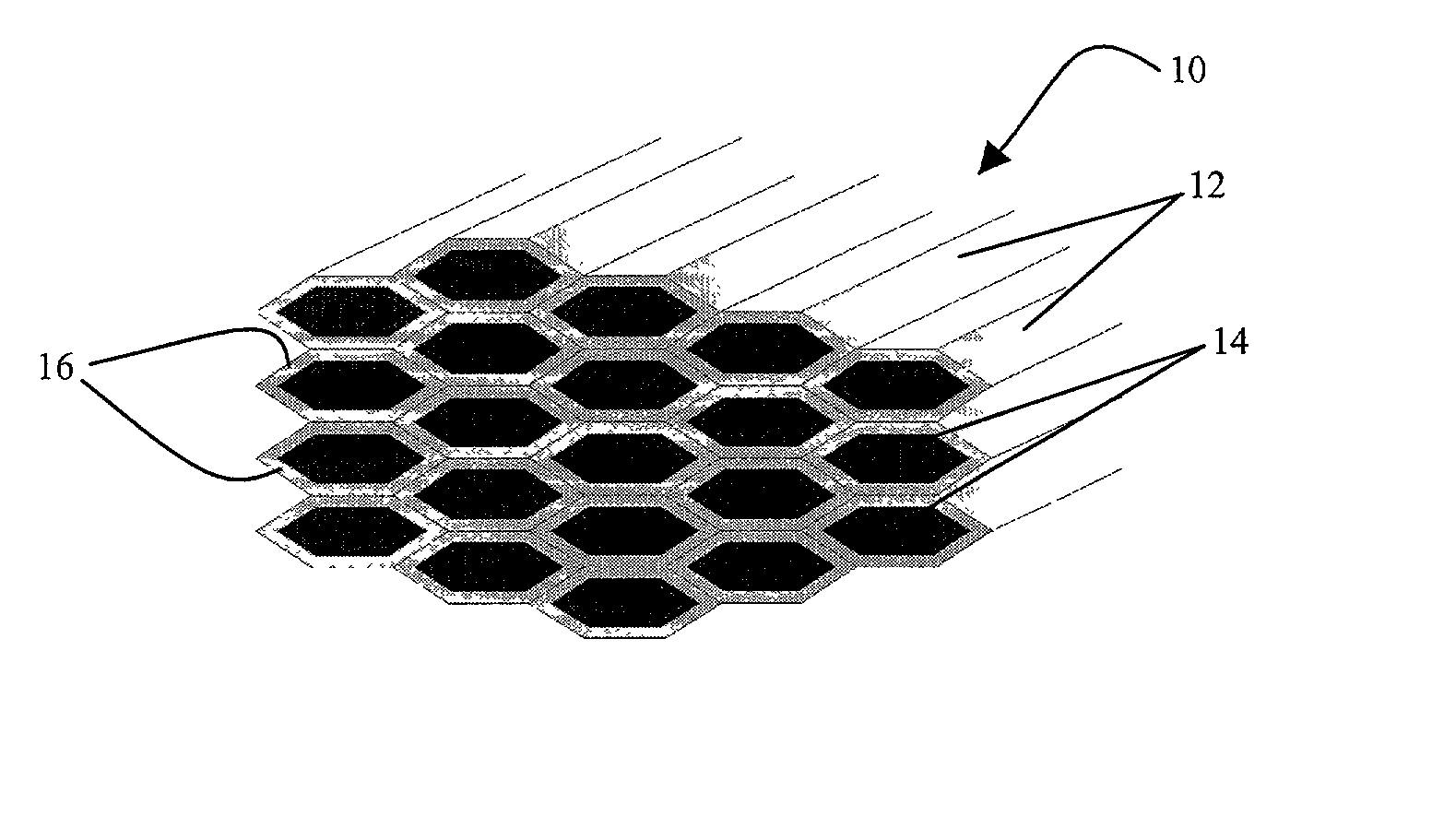
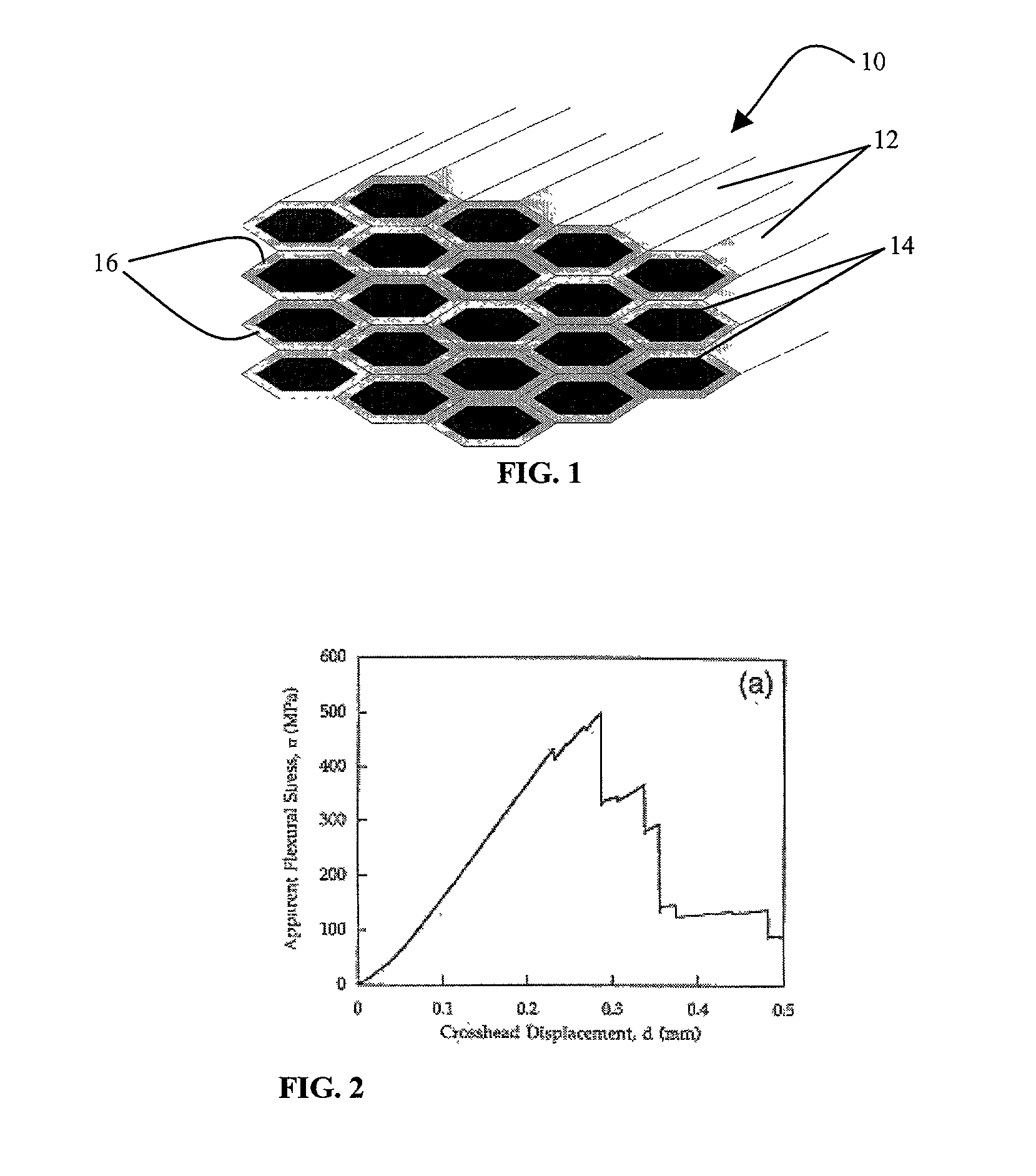
[0056] A multi-functional zirconium diboride / boron nitride / boron carbide (ZrB.sub.2 / BN / B.sub.4C) fibrous monolith composite is prepared in accordance with the present invention. In this composite, ZrB.sub.2 is the inner, first ceramic phase, BN is the boundary phase and B.sub.4C is the outer, second ceramic phase. The ZrB.sub.2 / BN / B.sub.4C tertiary FM composite system provides at least the following functions: strong structural material capable of withstanding high temperatures, higher fracture toughness as compared to monolithic ceramics, superior thermal shock resistance, power generation, and radiation hardening neutron absorber. The incorporation of an electrical power-generating function may allow for elimination or reduction of batteries or other means for generating electricity on board of a rocket or a hypersonic vehicle, resulting in decreased system complexity, increased reliability, and weight and cost savings. Boron's ability to absorb neutrons provides an additional ben...

example 2

[0057] The resulting mechanical properties of ZrB.sub.2 / BN / B.sub.4C as a structural composite include a combination of the properties of the constituent composites ZIRBORON.TM. and B.sub.4C and are influenced by the tertiary FM architectures. ZIRBORON.TM. fibrous monoliths have ZrB.sub.2 cells and BN cell boundaries. This FM material is an excellent refractory for high temperature oxidative and ablative environments, with good flexure strength, non-catastrophic failure, and high resistance to oxidation, very high melting point, and excellent thermal shock resistance. Basic properties of ZIRBORON.TM. FM material are presented in Table 2 below.

2TABLE 2 Thermal Shock Flexure Strength, .sigma. Total Work-of- Melting Resistance, 4-Point Fracture Point .DELTA.T = 2000.degree. C. 320 MPa 1174 J / m.sup.2 3000.degree. C. No Failure

[0058] The addition of B.sub.4C to the ZIRBORON.TM. system maintains the observed thermal and mechanical properties, because B.sub.4C is also a very good structural...

example 3

[0059] A ZrB.sub.2 / BN / B.sub.4C fibrous monolith was fabricated and consolidated by hot press at 1950.degree. C. Consolidation conditions for the ZrB.sub.2 / BN / B.sub.4C fibrous monolith are provided in Table 3. Mechanical property measurements are presented in Table 4.

3TABLE 3 Hot Press Hot Press FM Volume % of Pressure Consolidation Pressure Composition Constituants (MPa) Time (minutes) (MPa) ZrB.sub.2 / BN / B.sub.4C 50 / 25 / 25 27.58 60 27.58

[0060]

4TABLE 4 Archimedes Theoretical Measured Fracture FM Density EMOD EMOD Stress Composition (g / cm.sup.3) (GPa) (GPa) (MPa) ZrB.sub.2 / BN / B.sub.4C 4.172 .+-. 0.04 350 298.5 .+-. 17.3 227.1 .+-. 29.8


PUM

PropertyMeasurementUnit
Fractionaaaaaaaaaa
Densityaaaaaaaaaa
Pressureaaaaaaaaaa

Abstract

Fibrous monolith processing techniques to fabricate multifunctional structures capable of performing more than one discrete function such as structures capable of bearing structural loads and mechanical stresses in service and also capable of performing at least one additional non-structural function.

Description

CROSS-REFERENCE TO RELATED APPLICATIONS[0001] This application is based on, and claims the benefit of, co-pending United States Provisional Application Serial No. 60 / 251,212, filed on Dec. 4, 2000, and entitled "Smart Fibrous Monolith Multi-Functional Components," and co-pending United States Provisional Application Serial No. 60 / 293,595, filed on May 25, 2001, and entitled "A Method of Fabricating Electro-Mechanical Smart Structures Having Embedded Electrodes."FIELD OF THE INVENTION[0003] The present invention relates to fibrous monolith components capable of performing multiple functions and processes for preparing such components. More particularly, the present invention is directed to structures capable of more than one discrete function, such as those capable of bearing structural loads and mechanical stresses in service and also capable of performing non-structural functions, including strain measurement, power generation, and / or temperature measurement.BACKGROUND OF THE INVEN...

Claims


Application Information

Patent Timeline
IPC IPC(8): B29C48/05B29C48/06D06M11/83B29C48/12H01L41/08H01L41/18H01L41/333
CPCB29C48/30B29C48/12B29C48/304H01L41/082H01L41/1875H01L41/333B29C48/06Y10T428/249928Y10T428/249927Y10T428/249925Y10T428/249929Y10T428/2933Y10T428/249924B29C48/05H10N30/1061H10N30/8548H10N30/084
Inventor MULLIGAN, ANTHONY C.HALLORAN, JOHNPOPOVICH, DRAGANRIGALI, MARK J.SUTARIA, MANISH P.VAIDYANATHAN, K. RANJIFULCHER, MICHAEL L.KNITTEL, KENNETH L.
Owner ADVANCED CERAMICS
Why Eureka
Try Eureka