Method for producing film electrode jointed product and method for producing solid polymer electrolyte fuel cell

Inactive Publication Date: 2002-10-10
PANASONIC CORP +1
View PDF9 Cites 40 Cited by
  • Summary
  • Abstract
  • Description
  • Claims
  • Application Information

AI Technical Summary

Benefits of technology

0011] Accordingly, it is an object of the present invention to provide a novel production method which solves the foregoing problems of the prior art and is capable of eff

Problems solved by technology

It is, therefore, difficult to completely transfer the catalyst layers to the membrane, resulting in a low yield or a high probability that the thickness of each catalyst layer becomes non-uniform.
For this reason, a problem arises that it is difficult to adjust (make uniform) the amount of the catalyst in the plane direction of the membrane electrode assembly, hence, to obtain stable cell performance.
However, since such a gas diffusion layer is usually composed of porous carbon paper or carbon felt, a portion of uneven surface of the gas

Method used

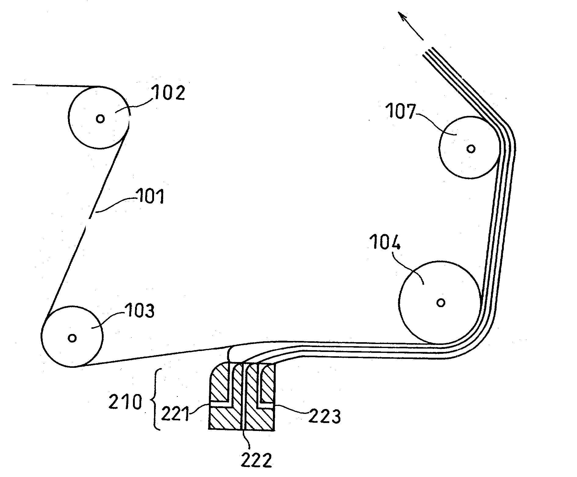
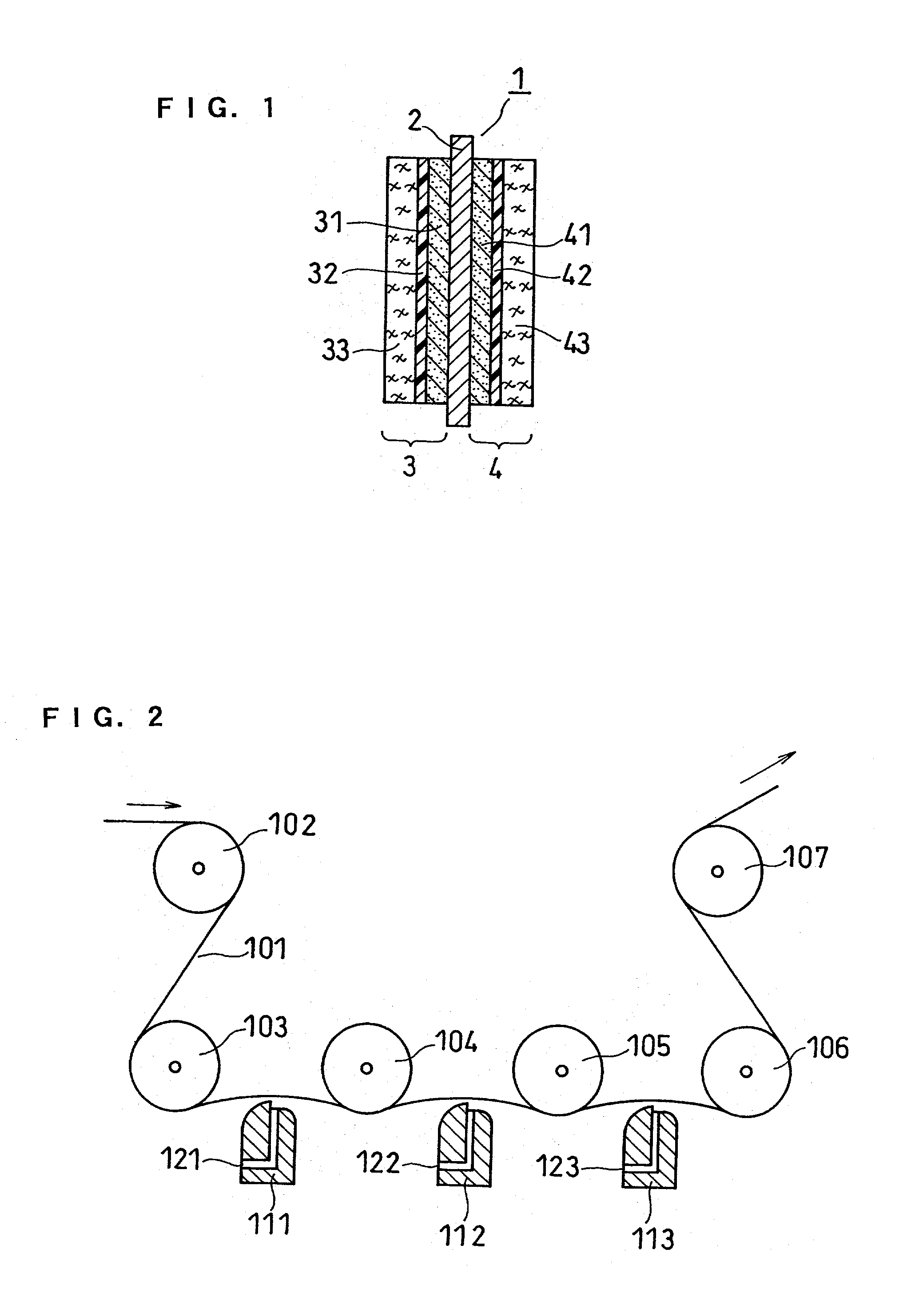

Image

  • Method for producing film electrode jointed product and method for producing solid polymer electrolyte fuel cell
  • Method for producing film electrode jointed product and method for producing solid polymer electrolyte fuel cell
  • Method for producing film electrode jointed product and method for producing solid polymer electrolyte fuel cell

Examples


example 2

[0084] A membrane electrode assembly was obtained in the same manner as in Example 1 except that the coating solution for forming an ion exchange membrane was applied by the die coater process and the thickness of an ion exchange membrane was made 15 .mu.m. The membrane electrode assembly thus obtained was incorporated into a cell for measuring cell performance in the same manner as in Example 1, and a test was conducted in the same manner as in Example 1. The results are shown in Table 1.

example 3

[0085] A membrane electrode assembly was obtained in the same manner as in Example 2 except that the coating solution for forming an ion exchange membrane was applied once by the die coater process, followed by drying naturally for 10 minutes, the coating solution for forming an ion exchange membrane was applied again thereover, followed by drying with an oven, and the thickness of an ion exchange membrane was made 30 .mu.m by such a two-time application. The membrane electrode assembly thus obtained was incorporated into a cell for measuring cell performance in the same manner as in Example 1, and a test was conducted in the same manner as in Example 1. The results are shown in Table 1.

example 4

[0086] After the formation of a first catalyst layer, an ion exchange membrane and a second catalyst layer on a PET film in the same manner as in Example 1, the resulting laminate was heat-treated with an oven at 120.degree. C. for 30 minutes and then the PET film was peeled off from the first catalyst layer. A membrane electrode assembly was obtained in the same manner as in Example 1 except that this heat treatment procedure was performed, and this assembly was incorporated into a cell for measuring cell performance to conduct a test in the same manner as in Example 1. The results are shown in Table 1.


PUM

PropertyMeasurementUnit
Areaaaaaaaaaaa
Thicknessaaaaaaaaaa

Abstract

A method for producing a membrane electrode assembly 1 for solid polymer electrolyte fuel cell, the membrane electrode assembly 1 including a solid polymer electrolyte membrane 2 comprising an ion exchange membrane, a first electrode 3 having a first catalyst layer 31, and a second electrode 4 having a second catalyst layer 41,the first electrode 3 and the second electrode 4 being disposed so as to be opposed to each other via the ion exchange membrane, the method including: applying a coating solution containing a catalyst onto a base film 101 to form a first catalyst layer 31; applying a coating solution containing an ion exchange resin dissolved or dispersed in a liquid onto the first catalyst layer 31 to form an ion exchange membrane; then applying a coating solution containing a catalyst onto the ion exchange membrane to form a second catalyst layer 41; and finally, peeling off the base film 101 from a resulting laminate. According to this method, it is possible to produce membrane electrode assembly 1 for high-performance solid polymer electrolyte fuel cell having catalyst layers each having a uniform thickness efficiently and continuously.

Description

[0001] The present invention relates to a method for producing a solid polymer electrolyte fuel cell as well as to a method for producing a membrane electrode assembly for solid polymer electrolyte fuel cell.[0002] Hydrogen / oxygen fuel cells produce in principle only water as their reaction product and hence receive attention as electric power generating systems that produce little adverse effect on the Earth's environment. Among them, solid polymer electrolyte fuel cells, in particular, are greatly expected to come in practice since their power density has been raised with rapid progress of study in recent years.[0003] Conventionally, such a solid polymer electrolyte fuel cell usually outputs power by the reaction between a fuel gas supplied to the anode side and an oxidant gas containing oxygen to the cathode side, respectively, of a membrane electrode assembly in which gas-diffusive electrodes each provided with a catalyst layer containing a catalyst and an ion exchange membrane ...

Claims


Application Information

Patent Timeline
IPC IPC(8): H01M4/88H01M8/10
CPCH01M4/8828Y10T29/49115Y02E60/521H01M8/1004Y02E60/50Y02P70/50H01M4/88
Inventor UCHIDA, MAKOTONIIKURA, JUNJIGYOTEN, HISAAKITAKEBE, YASUOHATOH, KAZUHITOHOSAKA, MASATOKANBARA, TERUHISAMUKOYAMA, ATSUSHISHIMODA, HIROSHIKINOSHITA, SHINJI
Owner PANASONIC CORP
Why Eureka
Try Eureka