Light guide plate made of transparent resin, molding method thereof, insert block, mold assembly, and area light apparatus

a technology of transparent resin and light guide plate, which is applied in the direction of moulds, cheese manufacture, butter manufacturing, etc., can solve the problems of difficult to form prism-shaped concave-convex portions in zirconia ceramics, the number of steps for assembling them is large, and the desired concave-convex portion or convex portion is accurately and reliably formed, and the desired concave-convex portion or convex portion is accurately and reliably

Inactive Publication Date: 2002-12-05
MITSUBISHI ENG PLASTICS CORP
View PDF11 Cites 74 Cited by
  • Summary
  • Abstract
  • Description
  • Claims
  • Application Information

AI Technical Summary

Benefits of technology

0022] It is a first object of the present invention to provide a light guide plate (light guiding plate) that has desired concave portions or convex portions accurately and reliably formed in its surface and is made of a transparent resin and a molding method of a light guide plate, an insert block that permits accurate and reliable formation...

Problems solved by technology

Meanwhile, a plurality of the prism sheets 355 have problems that they are expensive and that the number of steps for assembling them is large.
However, when the light guide plate 340 having the prism-shaped concavo-convex portion 342 in the surface is formed from a polycarbonate resin having poor flowability by an injection molding method, particularly, there is caused a problem that no prism-shaped concavo-convex portion can be formed in a surface portion of a light guide plate positioned far from a gate portion.
However, it is difficult to form a prism-shaped concavo-convex portion in zirconia ceramics, since the zirconia ceramics has high hardness and is fragile.
When an insert block is manufactured from zirconia ceramics and then the concavo-convex portion is mechanically formed in the surface of the insert block, it is difficult to form an intended shape or pattern.
Further, when the concavo-convex portion is mechanically formed in the surface concurrently with the formation of the insert block from zirconia ceramics, the insert block is liable to break due to a crack that occurs in the surface.
Particularly, the end portion of the insert block has a form weak in view of strength, so that there is caused a problem that when a stress is exerted on the end portion during assembling of a mold, the insert block is broken.
In a mold disclosed, for example, in JP-A-42650/1999, when a surface of an insert block and an insert-block-covering portion, facing such a surface of the insert block, have no sufficient high parallelism during clamping of the mold, there is a risk that the end portion of the insert block comes in contact with the insert-block-covering portion and, as a result, may be broken.
It is therefore difficult to cut zirconia ceramics with a general metal working machine.
Further, when it is cut (machined), the end portion of a cutting tool is liable to escape so that cutting is very difficult.
Further, when the insert block is constituted in a three-dimensional form, the problem is that metal machining of a mold portion near the insert-block-fitting portion is very difficult, so that it is required to rely on an ultra-precision working machine or a highly skilled worker.
Further, as the machining accuracy of the insert block increases, the production...

Method used


Image

  • Light guide plate made of transparent resin, molding method thereof, insert block, mold assembly, and area light apparatus
  • Light guide plate made of transparent resin, molding method thereof, insert block, mold assembly, and area light apparatus
  • Light guide plate made of transparent resin, molding method thereof, insert block, mold assembly, and area light apparatus

Examples


example 2

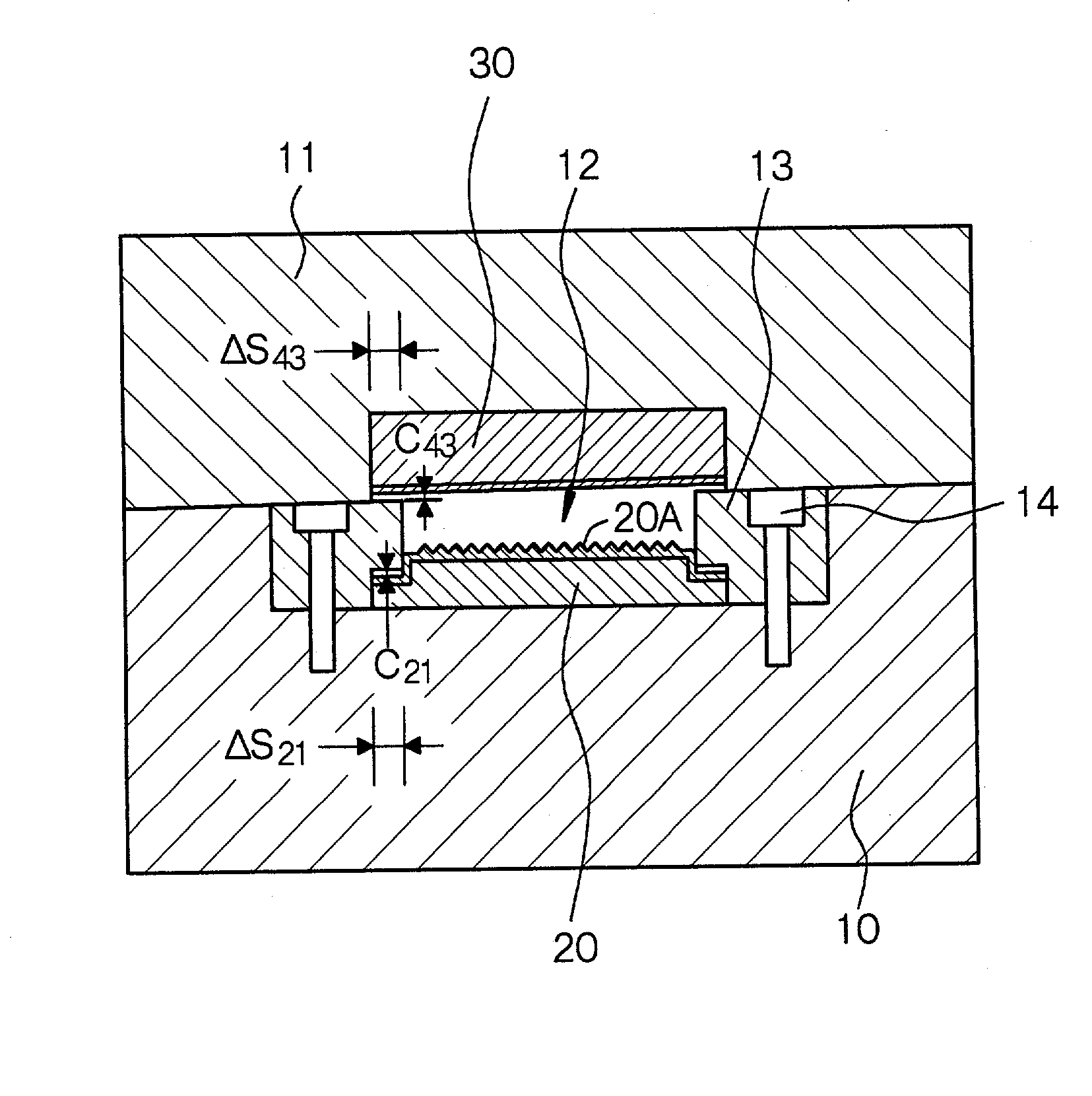
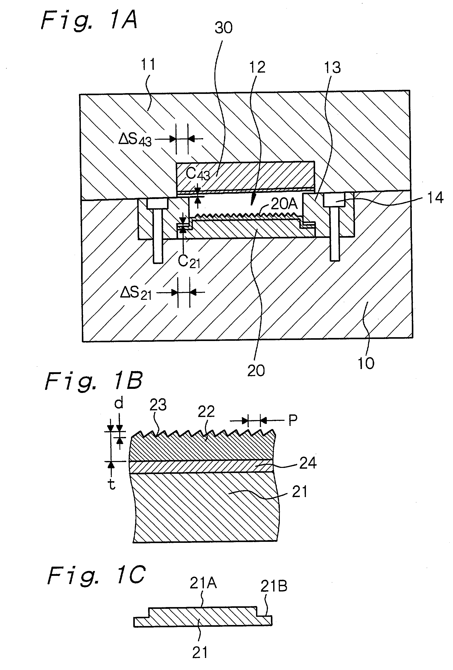
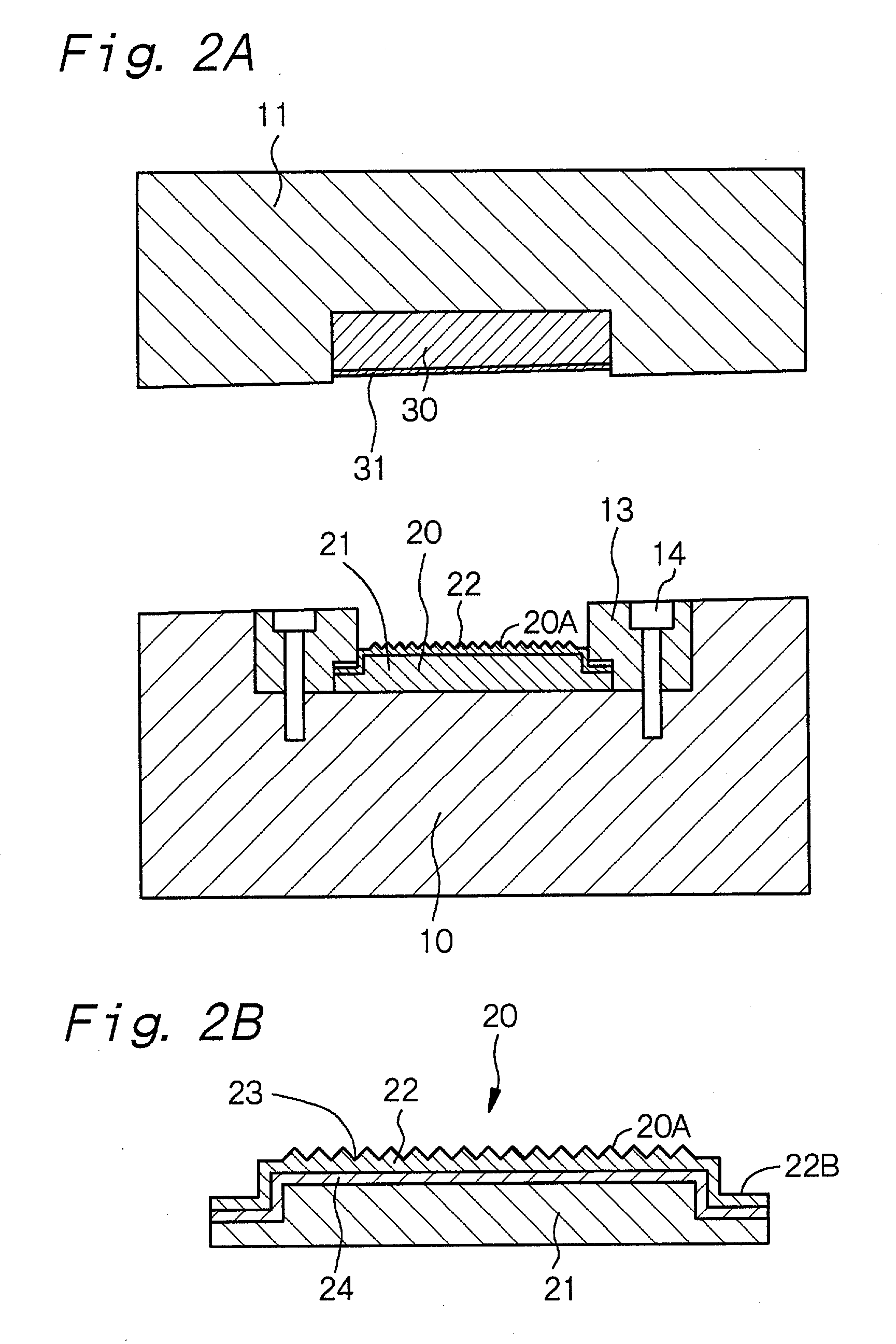
[0274] Example 2 is a variant of Example 1. An insert block 20 in Example 2 was fabricated by the following method. A second insert block 30 can be also fabricated by the same method.

[0275] First, a mixture of a zirconia powder and an yttrialite powder was press-molded and then calcined or sintered to prepare the insert block body 21. Then, that surface (surface 21A) of the insert block body 21 which faces the cavity 12 and that surface (surface 21B) which faces the cover plate 13 were subjected to blasting treatment using alumina particles, so that these surfaces 21A and 21B had a surface roughness R.sub.z of 2 .mu.m. Then, a 2 .mu.m thick Ni--P layer was formed on the above surfaces 21A and 21B of the insert block body 21 by an electroless plating method, then, a 5 .mu.m thick Ni layer was formed thereon by an electric plating method, and further, a 100 .mu.m thick Ni--P layer was formed thereon by an electroless plating method. Then, the Ni--P layer was machined using a diamond t...

example 3

[0279] Example 3 is also a variant of Example 1. Example 3 used partially stabilized electrically conductive zirconia ceramics to constitute an insert block body 21. Further, a metal layer 22 was formed on that surface 21A of the insert block body 21 which was to face the cavity. That is, specifically, the insert block 20 is made of partially stabilized zirconia (ZrO.sub.2--Y.sub.2O.sub.3) ceramics containing 8% by weight of Fe.sub.2O.sub.3 as an electrically conducting agent. Further, the content of Y.sub.2O.sub.3 as a partially stabilizing agent in the partially stabilized zirconia ceramics was 3 mol %. The above electrically conductive zirconia ceramics has a heat conductivity of approximately 3.8 J / (m.multidot.s.multidot.k) and a specific volume resistivity of 1.times.10.sup.8 .OMEGA..multidot.cm. The metal layer 22 is made of chromium (Cr). In Example 3, the metal layer 22 was formed on the entire surface of the insert block 20 by an electric plating method.

[0280] Other element...

example 4

[0281] Example 4 is also a variant of Example 1. In Example, a light guide plate 40 was molded by an injection compression molding method. FIG. 5 shows a schematic cross-sectional view of a mold assembly in Example 4. This mold assembly differs from the mold assembly explained in Example 1 in that a core 15 made of steel is provided in place of the second insert block and that a hydraulic cylinder 16 is provided for moving the core 15. The core 15 is allowed to move toward the insert block 20 with the hydraulic cylinder 16, whereby the volume of the cavity 12 can be varied. Other constitutions of the mold assembly can be the same as those of the mold assembly in Example 1, so that detailed explanations thereof are omitted.

[0282] In Example 4, the movement of the core 15 was 0.1 mm. Further, the light guide plate 40 had a large-thickness portion 45 having a thickness of 0.9 mm and a small-thickness portion 46 having a thickness of 0.7 mm. And, injection molding was carried out under ...


PUM

PropertyMeasurementUnit
Lengthaaaaaaaaaa
Lengthaaaaaaaaaa
Lengthaaaaaaaaaa

Abstract

A light guide plate which is made of a transparent resin and has a first main surface and a second main surface opposite to said first main surface, said first main surface having a surface portion provided with convex portions having a height of 5x10⁻⁷ m to 6x10⁻⁵ m each and a pitch of 5x10⁻⁷ m to 4x10⁻⁴ m, each convex portion having a tip portion, and the convex portions of at least 80% of the total convex portions having the tip portions having a radius of curvature of 2x10⁻⁶ m or less.

Description

BACKGROUND OF THE INVENTION AND RELATED ART STATEMENT[0001] The present invention relates to a light guide plate (light guiding plate) made of a transparent resin for a liquid crystal display in a personal computer, a cellular phone, PDA (personal digital assistant) and the like or for use in other fields, a molding method of a light guide plate, an insert block suitable for molding the above light guide plate, a mold assembly having the insert block suitable for molding the above light guide plate, and an area light apparatus (surface-emitting light source apparatus) having such a light guide plate.[0002] A liquid crystal display for use in a personal computer, a cellular phone, PDA and the like has an area light apparatus incorporated to cope with demands of a decrease in thickness, a decrease in weight, power saving, higher brightness and higher definition of the liquid crystal display. The area light apparatus generally has a wedge-shaped light guide plate having tapered slantin...

Claims


Application Information

Patent Timeline
IPC IPC(8): B29C33/38B29C33/42G02B6/00B29C45/26B29C45/37B29D11/00B29L11/00F21V8/00G02B6/08G02B6/12G02F1/1335G02F1/13357
CPCB29C45/372B29D11/00663B29L2011/0075G02B6/0038G02B6/0046G02B2006/12107G02B6/0055G02B6/0065G02B6/0071G02B6/08G02B6/005Y10S425/81
Inventor TAHARA, HISASHIKANEISHI, AKIMASA
Owner MITSUBISHI ENG PLASTICS CORP
Why Eureka
Try Eureka