System and method for building and manipulating a centralized measurement value database

a centralized measurement value and database technology, applied in the field of medical measurement value storage, can solve the problems of inconvenient remote user utilization of image data, inability to access measurement values generated by conventional isolated medical imaging diagnostic equipment, and inability to be used by remote users

Inactive Publication Date: 2002-12-12
IMAGING THERAPEUTICS +1
View PDF18 Cites 458 Cited by
  • Summary
  • Abstract
  • Description
  • Claims
  • Application Information

AI Technical Summary

Benefits of technology

[0224] The resulting market penetration data of different drugs in a particular region can be presented to users in various different ways. One such manner of presentation is illustrated in FIG. 5B. From the depiction in FIG. 5B, it can be seen that relatively large quantities of drug A are sold in California; that drug B has a relatively dominant position in states such as Missouri and Louisiana, while drug C appears to be prescribed predominantly in the Midwest and the east coast states. Through mining the central database of the present invention using known data mining techniques, authorized users of the central database, e.g., pharmaceutical companies, can determine areas where their drugs have relatively lower penetration, and where their drugs are underrepresented based on a particular demographic variable, and can adjust their marketing strategy accordingly.
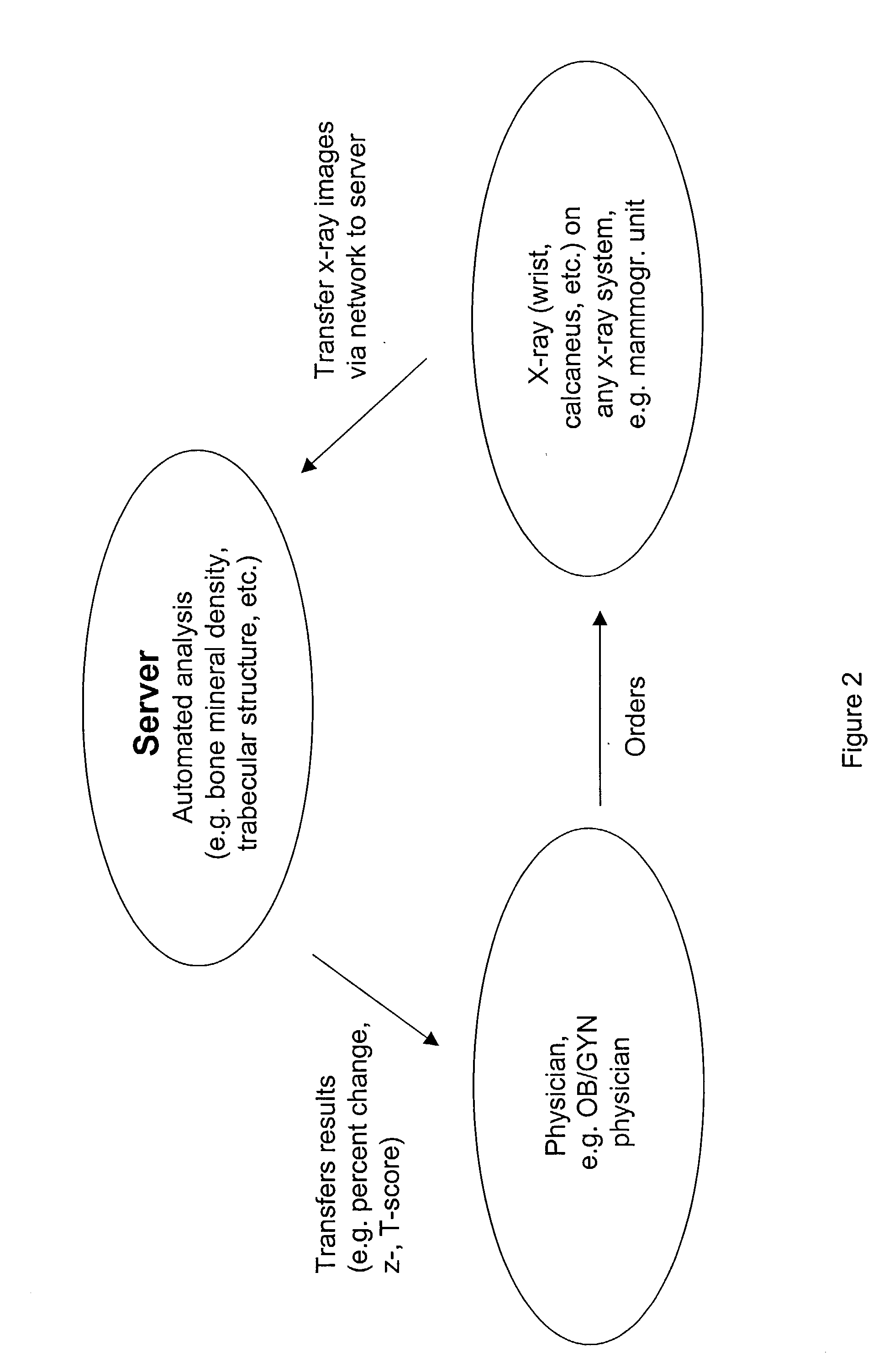
[0249] Although a wealth of information can be obtained from x-ray or other radiographic images alone, in certain embodiments the networked x-ray, ultrasound, CT, MRI, radionuclide, SPECT scan, PET scan or data derived from analysis of medical photographic techniques, laser enhanced imaging, and various biomicroscopy techniques or data from other medical tests include one or more accurate reference markers, for example calibration phantoms or reference standards, for example for assessing bone mineral density of a given x-ray image. Thus, in certain aspects, the current invention provides for methods and devices that allow accurate quantitative assessment of information contained in an x-ray, ultrasound, CT, MRI, radionuclide, SPECT scan, PET scan or data derived from analysis of medical photographic techniques, laser enhanced imaging, and various biomicroscopy techniques such as density of an anatomic structure or morphology of an anatomic structure in a network environment.
[0259] In certain embodiments, for example those embodiments in which the calibration phantom is temporarily attached to the x-ray assembly, cross-hairs, lines or other markers may be placed on the apparatus as indicators for positioning of the calibration phantom. These indicators can help to ensure that the calibration phantom is positioned such that it doesn't project on materials that will alter the apparent density in the resulting image.
[0261] FIG. 8 shows a film packet (11) for holding x-ray film. Film packet (11) is within a bite wing film holder (10) that has a bite tab (12) extending perpendicular from the film holder (11). The opening (13) allows alignment on a patient's teeth. As shown, the bite tab (12) has a generally square shape. A curved cutaway portion (20) along one edge can be included to allow better aiming of the x-ray tube. A calibration phantom can be positioned in any suitable location on the holder or film following the teachings described herein. In some embodiments, it is desirable that the calibration phantom be positioned so it does not project on structures or materials that will alter the apparent density of the calibration phantoms. It is also desirable that the calibration phantom includes a marker (e.g, geometric pattern) at a known density to increase the accuracy of the phantom as an external standard. For example, in dental x-rays, the calibration phantom can be positioned where the bite wing (12) meets the film holder (11), for example near the bend (18) or along the area (8) created where the bite wing (12) meets the film holder (11). Such careful positioning ensures that the calibration phantom will appear in the x-ray image between the teeth and, therefore, will be more accurate than if bone (e.g., jaw) or teeth. It will be readily apparent that the area containing the calibration phantom can be made slightly thicker to ensure that the calibration phantom does not project on bone or dental tissue in the x-ray image.

Problems solved by technology

However, the measurement values generated by conventional isolated medical imaging diagnostic equipment often are inaccessible to remote users, with images being available either as developed films, or stored in hard drives in the equipment.
As a result, it can be inconvenient for remote users to utilize the data contained in those images for disease diagnosis and epidemiological analysis.
It also may be impractical to use the measurement values, separately stored in that isolated equipment, to perform regional comparisons to determine the prevalence of diseases and to perform statistical analysis of the measurement values.
In addition, known medical imaging diagnostic systems do not collect and store subjects' treatment information, and therefore cannot track improvements in subjects' conditions as a result of various treatments, and compare the therapeutic efficacy of different drugs.
These conventional systems also cannot provide pharmaceutical manufacturers with useful marketing strategy information, to help identify potential or growing markets for given drugs, and current market share information for different drugs.
Known medical imaging diagnostic systems do not provide for remote quality assurance of image quality.

Method used


Image

  • System and method for building and manipulating a centralized measurement value database
  • System and method for building and manipulating a centralized measurement value database
  • System and method for building and manipulating a centralized measurement value database

Examples


Embodiment Construction

[0022] Before describing the present invention in detail, it is to be understood that this invention is not limited to particular formulations or process parameters as such may, of course, vary. It is also to be understood that the terminology used herein is for the purpose of describing particular embodiments of the invention only, and is not intended to be limiting.

[0023] The practice of the present invention employs, unless otherwise indicated, conventional methods of database storage and manipulation, within the skill of the art. Such techniques are explained fully in the literature. See, e.g., Numerical Mathematical Analysis, Third Edition, by J. B. Scarborough, 1955, John Hopkins Press, publisher; System Analysis and Design Methods, by Jeffrey L. Whitten, et al., Fourth Edition, 1997, Richard D. Irwin, publisher; Modem Database Management, by Fred R. McFadden, et al., Fifth Edition, 1999, Addison-Wesley Pub. Co., publisher; Modem System Analysis and Design, by Jeffery A. Hoffe...


PUM

PropertyMeasurementUnit
ultrasoundaaaaaaaaaa
CTaaaaaaaaaa
MRIaaaaaaaaaa

Abstract

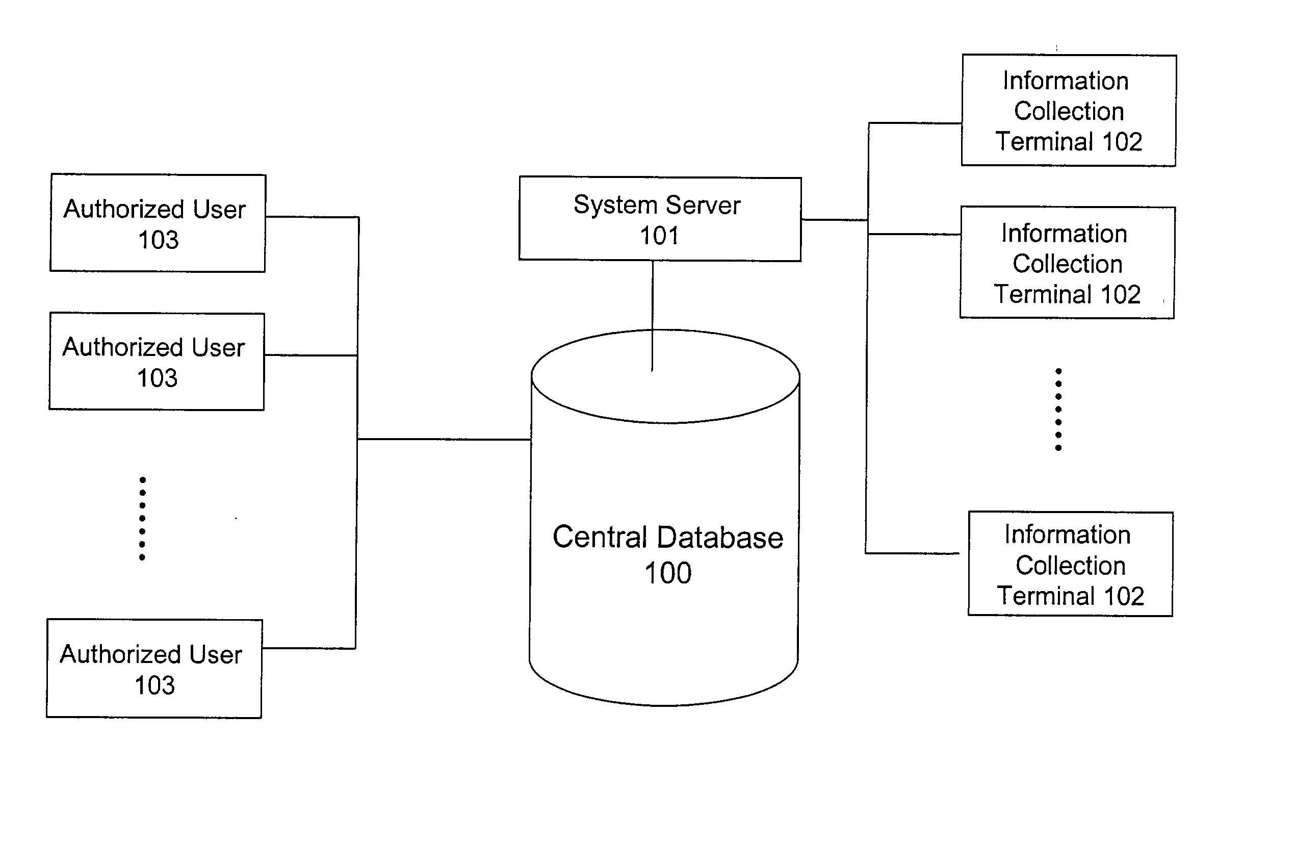
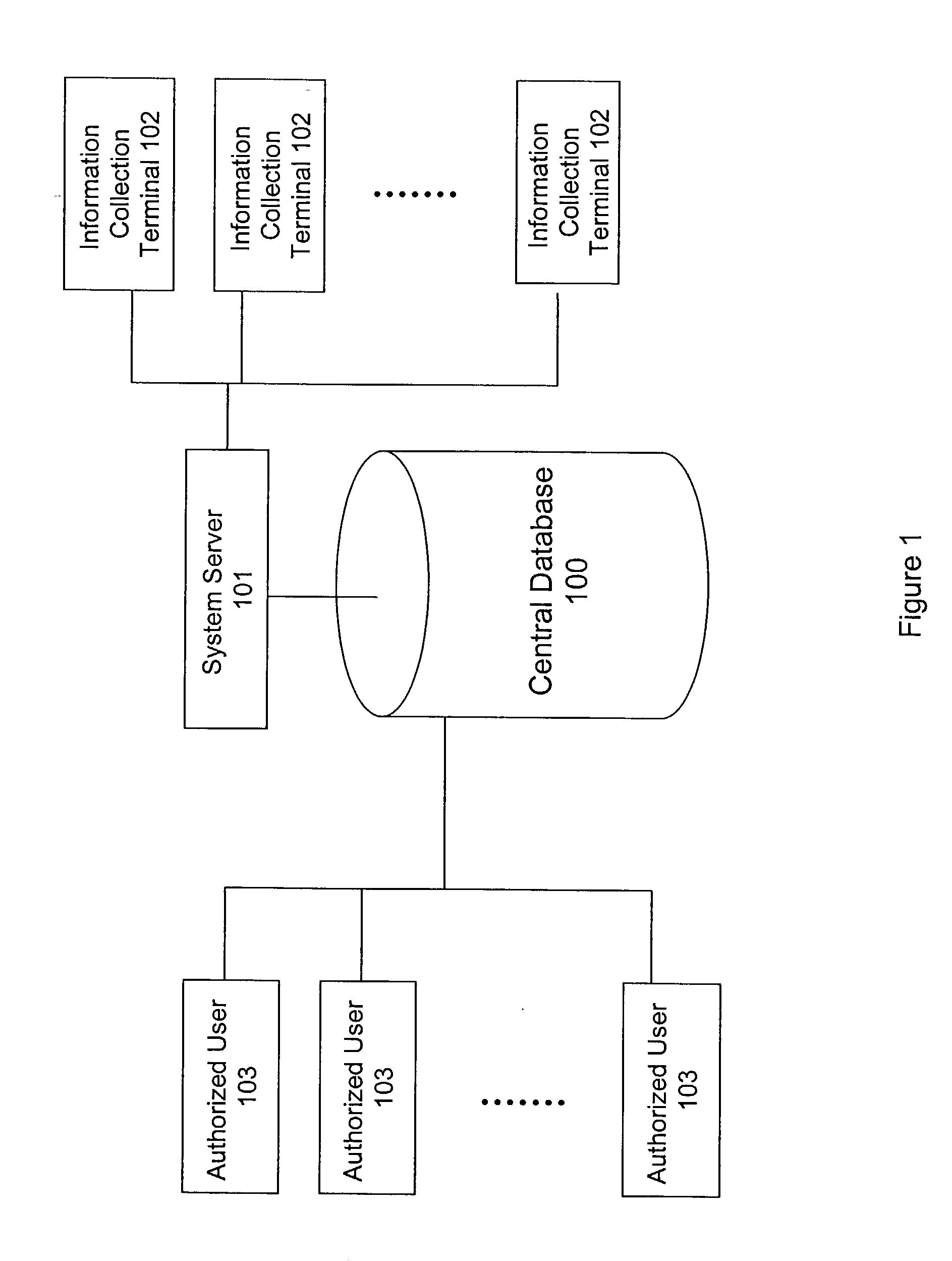
A system and method for building and / or manipulating a centralized medical image quantitative information database aid in diagnosing diseases, identifying prevalence of diseases, and analyzing market penetration data and efficacy of different drugs. In one embodiment, the diseases are bone-related, such as osteoporosis and osteoarthritis. Subjects' medical images, personal and treatment information are obtained at information collection terminals, for example, at medical and / or dental facilities, and are transferred to a central database, either directly or through a system server. Quantitative information is derived from the medical images, and stored in a central database, associated with subjects' personal and treatment information. Authorized users, such as medical officials and / or pharmaceutical companies, can access the database, either directly or through the central server, to diagnose diseases and perform statistical analysis on the stored data. Decisions can be made regarding marketing of drugs for treating the diseases in question, based on analysis of efficacy, market penetration, and performance of competitive drugs.

Description

REFERENCE TO RELATED APPLICATIONS[0001] This application is a continuation-in-part of U.S. patent application Ser. No. 09 / 942,528, filed Aug. 29, 2001, and entitled METHODS AND DEVICES FOR QUANTITATIVE ANALYSIS OF MEDICAL IMAGES, which claims the benefit under 35 U.S.C. .sctn.119(e) of U.S. Provisional Patent Application No. 60 / 228,591, filed Aug. 29, 2000. These applications are incorporated by reference into the present application.[0002] 1. Field of the Invention[0003] The present invention relates generally to storage of medical measurement values, and more particularly, to a method and system for collecting, processing, and storing medical data derived from medical images, or other diagnostic information, and related patient and treatment information, to diagnose diseases, and to enable analysis of drug efficacy and market penetration for different drugs.[0004] 2. Description of the Related Art[0005] X-rays and other medical imaging techniques are important diagnostic tools. Ho...

Claims


Application Information

Patent Timeline
Patent Type & Authority Applications(United States)
IPC IPC(8): A61B5/00A61B6/00G01N23/00G01N23/05G01T1/24G06FG06K9/00G06Q30/02G06T7/00G16H10/60H05G1/28H05G1/64
CPCA61B6/505A61B6/508A61B6/583G06F19/321G06F19/322G06F19/3431G06F19/3493G06K2009/00946G06Q30/02G06Q50/22G06Q50/24G06T7/0018G06T2207/10116G06T2207/30036A61B5/7264A61B6/4423A61B5/002A61B5/0022A61B6/563G06T7/80G16H10/60G16H50/30G16H50/80G16H20/10G16H30/20G06V40/155
Inventor ARNAUD, CLAUDELINDER, BARRY J.STEINES, DANIELLANG, PHILIPP
Owner IMAGING THERAPEUTICS
Why Eureka
Try Eureka