Process for making a fuel cell with cylindrical geometry

a fuel cell and cylindrical technology, applied in the direction of fuel cells, coatings, cells, etc., can solve the problems of low catalyst dispersion, difficult assembly of micro-electrodes with thin ionic conducting films, and limited performance of this type of devices

Inactive Publication Date: 2003-01-30
COMMISSARIAT A LENERGIE ATOMIQUE ET AUX ENERGIES ALTERNATIVES
View PDF13 Cites 13 Cited by
  • Summary
  • Abstract
  • Description
  • Claims
  • Application Information

AI Technical Summary

Problems solved by technology

The difficulty lies in the assembly of the micro-electrode with the thin ionic conducting film.
However, the performances of this type of device are limited by the bad cohesion of the different layers, thus creating a high interface resistance, and consequently a very low dispersion of the catalyst, the catalyst being finely divided, in order to obtain a strongly electronic conducting deposit.
This technique has a number of disadvantages, particularly related to the properties of nickel.
Furthermore, the catalyst is also only weakly dispersed at the perforated nickel layer, which has a low ability to entrain a homogeneous dispersion of the reducing agent on the catalyst.
Finally, with this technology, the probability of the presence of triple points is low.
This invention has two main disadvantages, firstly the fragility of the polymer substrate particularly when it is treated by aggressive vacuum deposition techniques, and secondly poor electrochemical performances related particularly to the lack of active area, and also the fragility of the catalyst deposit made directly on proton exchanging membranes.
All these described architectures have the special feature that they are all flat and consequently cannot give a sufficiently large electrode surface area to supply portable electronic devices with energy.
However, the performances of this type of assembly are limited mainly for two reasons:
the electrode-membrane-electrode assembly, which is initially flat is not adapted to a cylindrical geometry, which means that it is almost impossible to restore anode-anode, cathode-cathode and membrane-membrane contacts after winding the flat electrode-membrane-electrode assembly;
current collectors are not in intimate contact with the anode and the cathode, thus generating excessively high interface resistances.
However, this type of architecture is not suitable for portable electronic equipment mainly due to the resulting size, due to the use of the "cylinder-holder" system.

Method used


Image

  • Process for making a fuel cell with cylindrical geometry
  • Process for making a fuel cell with cylindrical geometry
  • Process for making a fuel cell with cylindrical geometry

Examples


Embodiment Construction

[0019] The purpose of this invention is to overcome the above disadvantages by proposing a process for the preparation of an electrode-membrane-electrode assembly, to be used in the composition of a low or medium power membrane fuel cell in order to obtain a high electrode surface area in a small volume.

[0020] Another purpose of this invention is to propose a process capable of obtaining an electrode-membrane-electrode assembly with good electrical contacts, thus overcoming the disadvantages of prior art for a cylindrical type architecture and to obtain a reagents distribution area at the end of the said process.

[0021] Finally, another purpose of the invention is to supply compact electrode-membrane-electrode assemblies to be used in the composition of fuel cells in order to supply power to portable electronic equipment.

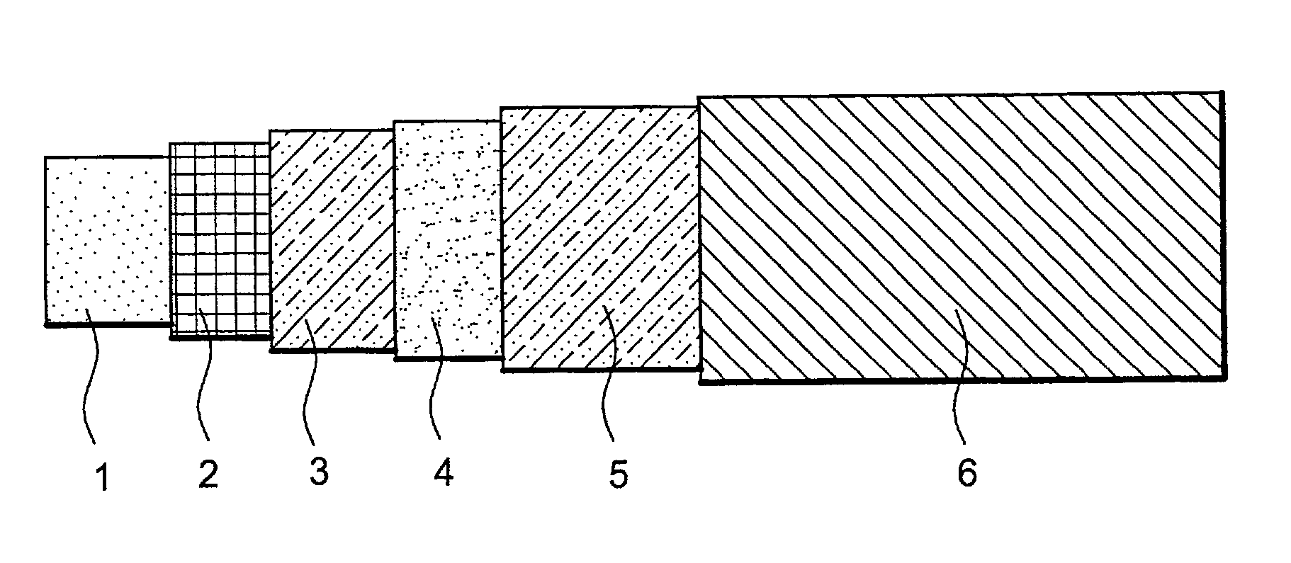
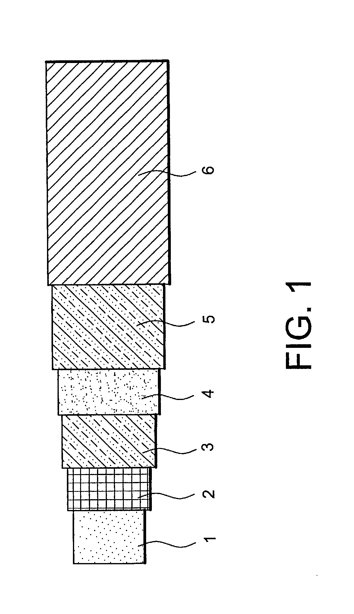
[0022] In order to achieve this, the purpose of the invention is a process for making an electrode-membrane-electrode assembly on a cylindrical substrate, characteri...


PUM

PropertyMeasurementUnit
porosityaaaaaaaaaa
porosityaaaaaaaaaa
porosityaaaaaaaaaa

Abstract

The invention relates to a process for production of an electrode-membrane-electrode assembly on a cylindrical substrate (1), characterized in that the electrode-membrane-electrode assembly is made by successively depositing an electrode layer (2, 3), a membrane layer (4) and an electrode layer (5, 6) around the said cylindrical substrate, the said substrate being composed of a material that can be totally or partially eliminated during an elimination step at the end of the said process. The invention also relates to an electrode-membrane-electrode assembly obtained by the said process and a fuel cell comprising at least one such electrode-membrane-electrode assembly.

Description

TECHNICAL DOMAIN[0001] This invention relates to a process for making a cylindrical fuel cell architecture, more particularly an electrode-membrane-electrode assembly.[0002] The invention also relates to a cell comprising such an assembly.[0003] In general, a fuel cell is composed of a combination of elementary cells (each elementary cell consisting of an electrode-membrane-electrode assembly) resulting from a stack of layers. These layers are composed of electrode layers and electrolyte layers (called membrane layers when the electrolyte is a solid polymer). Each electrode layer may itself be composed of three thin layers:[0004] a diffusion layer, usually made of porous carbon used to carry the input current and act as a mechanical support for the electrode and enabling good distribution of reagents to the active layer;[0005] an active layer, in which the electrochemical reaction takes place and is usually composed of a carbon powder supporting catalyst particles, all being impregn...

Claims


Application Information

Patent Timeline
Patent Type & Authority Applications(United States)
IPC IPC(8): C25B9/23H01M4/86H01M4/88H01M4/92H01M8/1004
CPCC25B9/10H01M4/8605H01M4/8814H01M4/92H01M8/1004Y02E60/521Y02P70/50Y02E60/50C25B9/23
Inventor MARSACQ, DIDIERLAURENT, JEAN-YVESBLOCH, DIDIERNAYOZE, CHRISTINE
Owner COMMISSARIAT A LENERGIE ATOMIQUE ET AUX ENERGIES ALTERNATIVES
Why Eureka
Try Eureka