
Device and method for integrated diagnostics with multiple independent flow paths

a technology of integrated diagnostics and flow paths, applied in specific use bioreactors/fermenters, instruments, biomass after-treatment, etc., can solve the problems of unidirectional flow, different wash and substrate reagents, and inability to use enzyme amplified assays, etc., to achieve the control of the delivery of clean wash solution, reduce non-specific binding, and increase assay performance

Inactive Publication Date: 2003-02-27
CLARK SCOTT M +4
View PDF36 Cites 36 Cited by
  • Summary
  • Abstract
  • Description
  • Claims
  • Application Information

AI Technical Summary

Benefits of technology

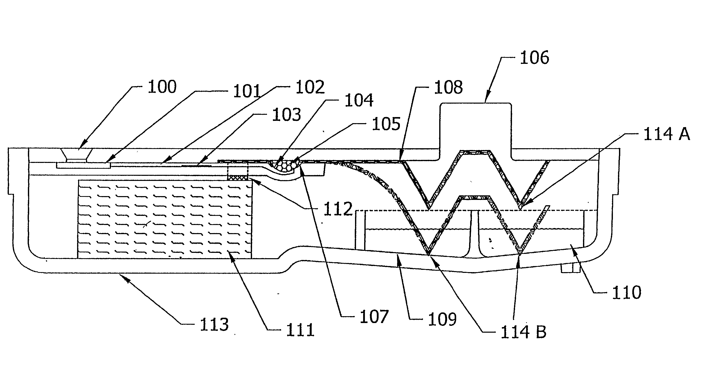
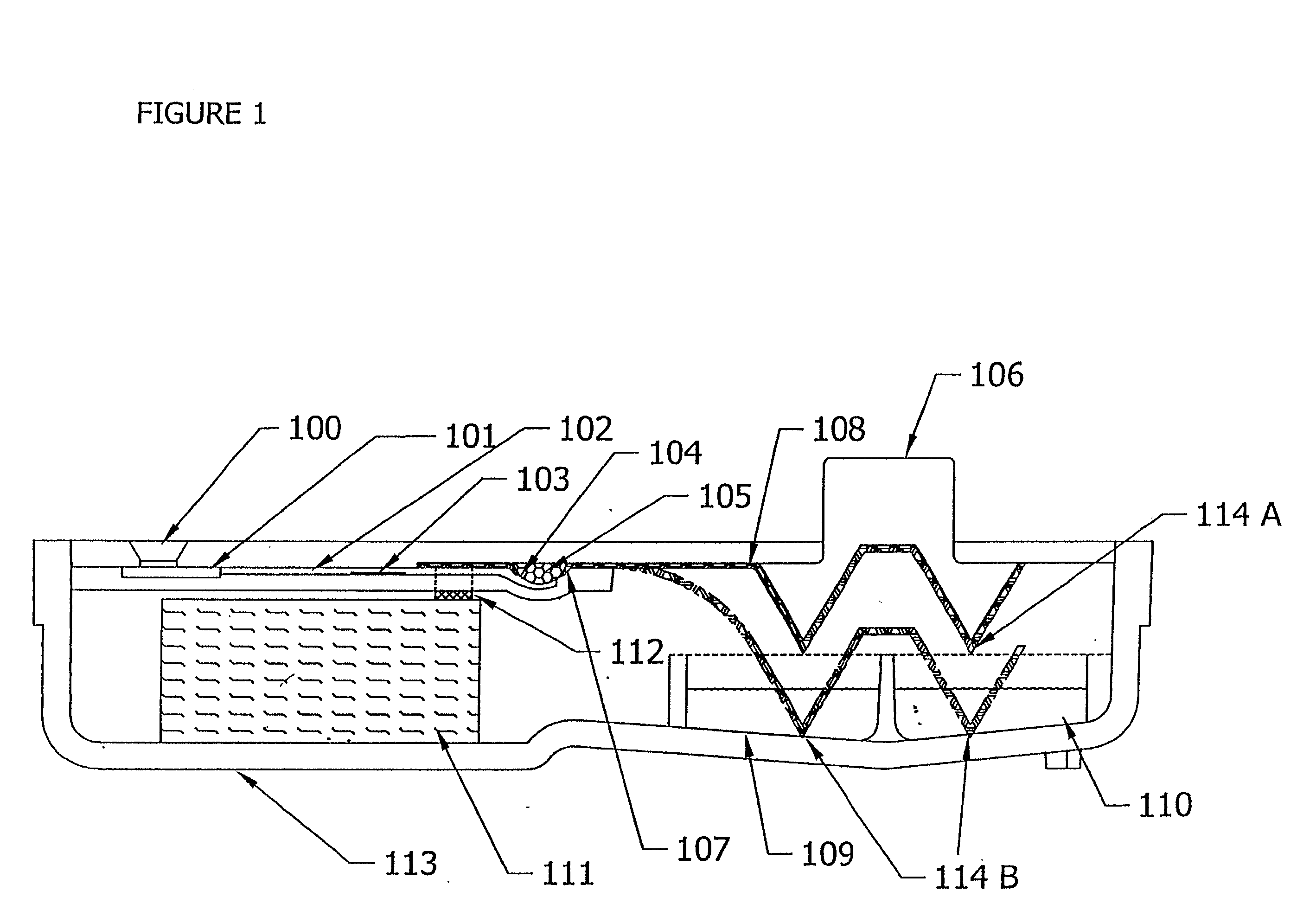
[0028] The volume of sample delivered by this first path is determined by the absorbent capacity of the solid phase, and not by the amount of sample added to the device, relieving the user from the necessity of measuring the sample. The sample / conjugate mixture is prevented from entering the second flow path because the capillarity and the surface energy of the second flow path prevent it from being wetted by this mixture.
[0137] In a quantitative assay, precision and enhanced sensitivity may be achieved by precisely controlling the timing steps of the reaction. The precision of this assay device may be improved by developing an instrument that controls the time that the sample resides in the sample delivery channel, the time the sample / reagent mixture resides in the solid phase, and the time after washing that the assay is read.

Problems solved by technology

In assay methods using such devices, fluid flow is unidirectional and reaction and detection occur in distinct zones.
Likewise, Buechler does not teach or suggest the creation of a second flow path.
The methods and devices of Buechler et al. do not allow one to use multiple reagents, different wash and substrate reagents and cannot be used in an enzyme amplified assay.
Other disadvantages of this device are that it (1) does not teach or suggest a defined fluid path for residual sample or wash, (2) does not permit controlled delivery of predetermined amounts of reaction components or wash, and (3) does not permit sequential delivery of such components.
The mechanism for reversing flow does not allow for automated timing.

Method used


Image

  • Device and method for integrated diagnostics with multiple independent flow paths
  • Device and method for integrated diagnostics with multiple independent flow paths
  • Device and method for integrated diagnostics with multiple independent flow paths

Examples


example 2

[0159] The device of example 1 can be simplified by use of a fluorescent label or colored particle e.g. colloidal gold, attached to the chicken anti-heartworm antibody instead of using HRP as the conjugate. In this case, the substrate reagent can be omitted, and the signal is viewed after the unbound reagent is washed away.

example 3

[0160] To detect multiple analytes in a single sample, a multi-channel device is constructed from the device in example 1 by feeding multiple sample delivery channels from a single sample entry port (FIG. 7). Each sample delivery channel will contain different conjugate binding reagents to detect the different analytes. Thus, four solid-phase containers are constructed to be adjacent to each other. The assembly is attached to a plastic part with four sample delivery channels.


PUM

PropertyMeasurementUnit
widthsaaaaaaaaaa
widthsaaaaaaaaaa
lengthsaaaaaaaaaa

Abstract

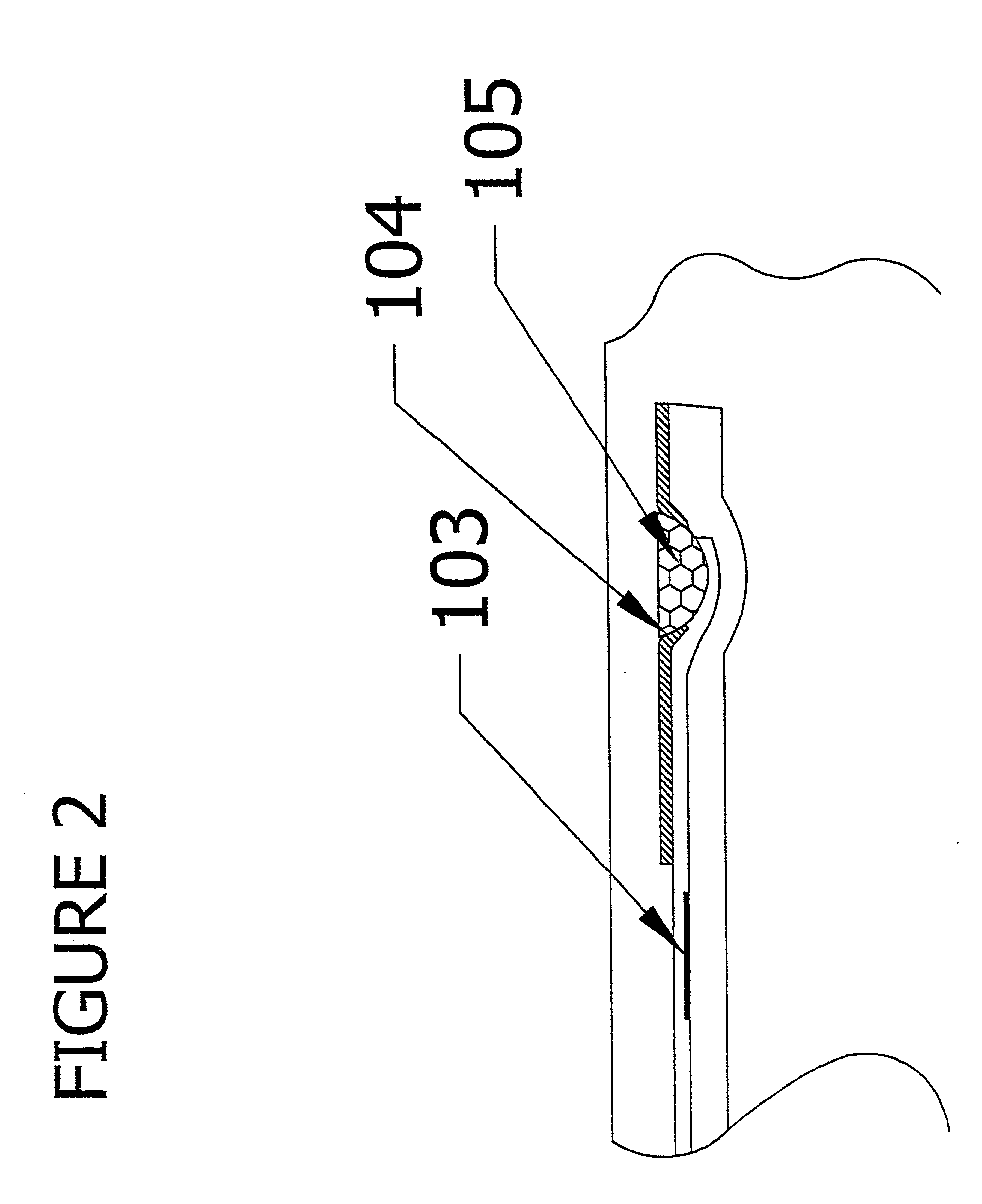
Devices and methods for performing assays to determine the presence or quantity of a specific analyte of interest in a fluid sample. In devices according to this invention two separate flow paths are established sequentially in the device with a single user activation step. The first flow path delivers the analyte of interest (if present in the sample) and conjugate soluble binding reagents to the solid phase. If analyte is present, an analyte:conjugate complex is formed and immobilized. The volume of sample delivered by this first path is determined by the absorbent capacity of the solid phase, and not by the amount of sample added to the device, relieving the user from the necessity of measuring the sample. The sample / conjugate mixture is prevented from entering the second flow path because the capillarity and the surface energy of the second flow path prevent it from being wetted by this mixture. The second flow path allows a wash reagent to remove unbound conjugate and sample from the solid phase to the absorbant, and optionally to deliver detection reagents. The invention may be adapted to many assay formats including, sandwich immunoassays, colloidal gold, or sol particle assays, heterogeneous generic capture assays and competitive assays. In one embodiment, sandwich assays can be performed by immobilizing an analyte binding reagent on the solid phase, and drying a labeled analyte binding reagent in the first flow path. In a competitive assay embodiment, the first flow path would contain labeled analyte that is dissolved by the sample, and the analyte binding reagent is immobilized on the solid phase. In each of these embodiments, the assay can be further modified to run in a "generic capture" format, where the solid phase binding reagent is instead conjugated to a generic ligand such as biotin, and dried in the first flow path (either together or separately from the other assay reagents), and a generic ligand binding reagent (such as avidin) is immobilized on the solid phase. Another aspect of the present invention includes a subassembly for the immunoassay device that is comprised of a plastic housing and a means for delivering fluid and / or wash solution. This subassembly comprises a structure formed from a hydrophobic polymer selectively treated with a water insoluble surface active agent that has been applied as a solution in an organic solvent rendering portions of the surface hydrophilic. When the surface is contacted with an aqueous liquid, it flows only along the treated areas, creating a defined fluid flow path, thereby delivering sample / conjugate solutions to said solid phase.

Description

[0001] 1. Field of the Invention[0002] This invention relates to devices and methods for performing assays to determine the presence or quantity of a specific analyte of interest in a fluid sample. Devices of this invention assay a measured amount of sample employing at least two separate and distinct flow paths which are initiated simultaneously with a single user activation step. These paths are timed for the sequential delivery of assay reagents to the reaction zone, followed by wash or substrate and wash reagents to that zone. These inventive devices and methods may be used for qualitative, semi-quantitative and quantitative determinations of one or multiple analytes in a single test format. They may be practiced with ELISA, sol particle and other assay formats, and are particularly suitable for simultaneous multiple analyte assays. These inventive devices and methods provide for the controlled, self delivery of reagents with no timed steps, and minimal user intervention, in mos...

Claims


Application Information

Patent Timeline
Patent Type & Authority Applications(United States)
IPC IPC(8): G01N33/566C12M1/00C12Q1/68G01N33/53G01N33/543G01N33/558G01N37/00
CPCG01N33/54366G01N33/558Y10T436/12Y10T436/255Y10T436/11G01N33/54388
Inventor CLARK, SCOTT M.SUVA, ROBERT H.KEPRON, MICHAEL R.BARSKI, STANISLAW JR.WORKMAN, ERWIN F. JR.
Owner CLARK SCOTT M
Learn More