Continuous fiber reinforced composites and methods, apparatuses, and compositions for making the same

a technology composites, applied in the direction of synthetic resin layered products, process and machine control, program control, etc., can solve the problems of low fracture toughness, limited use of fiber reinforced composites in stressed environments, and inability to withstand extreme damag

Inactive Publication Date: 2003-03-06
ADVANCED CERAMICS
View PDF15 Cites 157 Cited by
  • Summary
  • Abstract
  • Description
  • Claims
  • Application Information

AI Technical Summary

Problems solved by technology

However, monolithic ceramics have one property that limits their use in stressed environments, namely their low fracture toughness.
While significant advances have been made to improve the fracture toughness of monolithic ceramics, mostly through the additions of whisker and particulate reinforcements or through careful control of the microstructural morphology, they still remain extremely damage intolerant.
More specifically, they are susceptible to thermal shock and will fail catastrophically when placed in severe stress applications.
Even a small processing flaw or crack that develops in a stressed ceramic cannot redistribute or shed its load on a local scale.
Under high stress or even mild fatigue, the crack will propagate rapidly resulting in catastrophic failure of the part in which it resides.
It is this inherently brittle characteristic which can be even more pronounced at elevat...

Method used


Image

  • Continuous fiber reinforced composites and methods, apparatuses, and compositions for making the same
  • Continuous fiber reinforced composites and methods, apparatuses, and compositions for making the same
  • Continuous fiber reinforced composites and methods, apparatuses, and compositions for making the same

Examples


example 1

[0078] Hafnium Carbide Matrix / No Interface / Carbon Fiber Reinforcement

[0079] VPCA-BROO

[0080] Description: Core Material

[0081] Brabender Size: small

[0082] Batch Size: 42 cc

[0083] Batch Temperature: 150.degree. C.

[0084] Batch Speed: 60 rpm

[0085] Ingredients:

3TABLE 3 Material Density (g / cc) Volume % Volume (cc) Weight (g) HfC 12.67 54.0% 22.66 287.36 EEA 0.93 32.4% 13.608 12.66 B-67 0.94 3.6% 1.512 1.42 HMO 0.881 10.0% 4.2 3.70

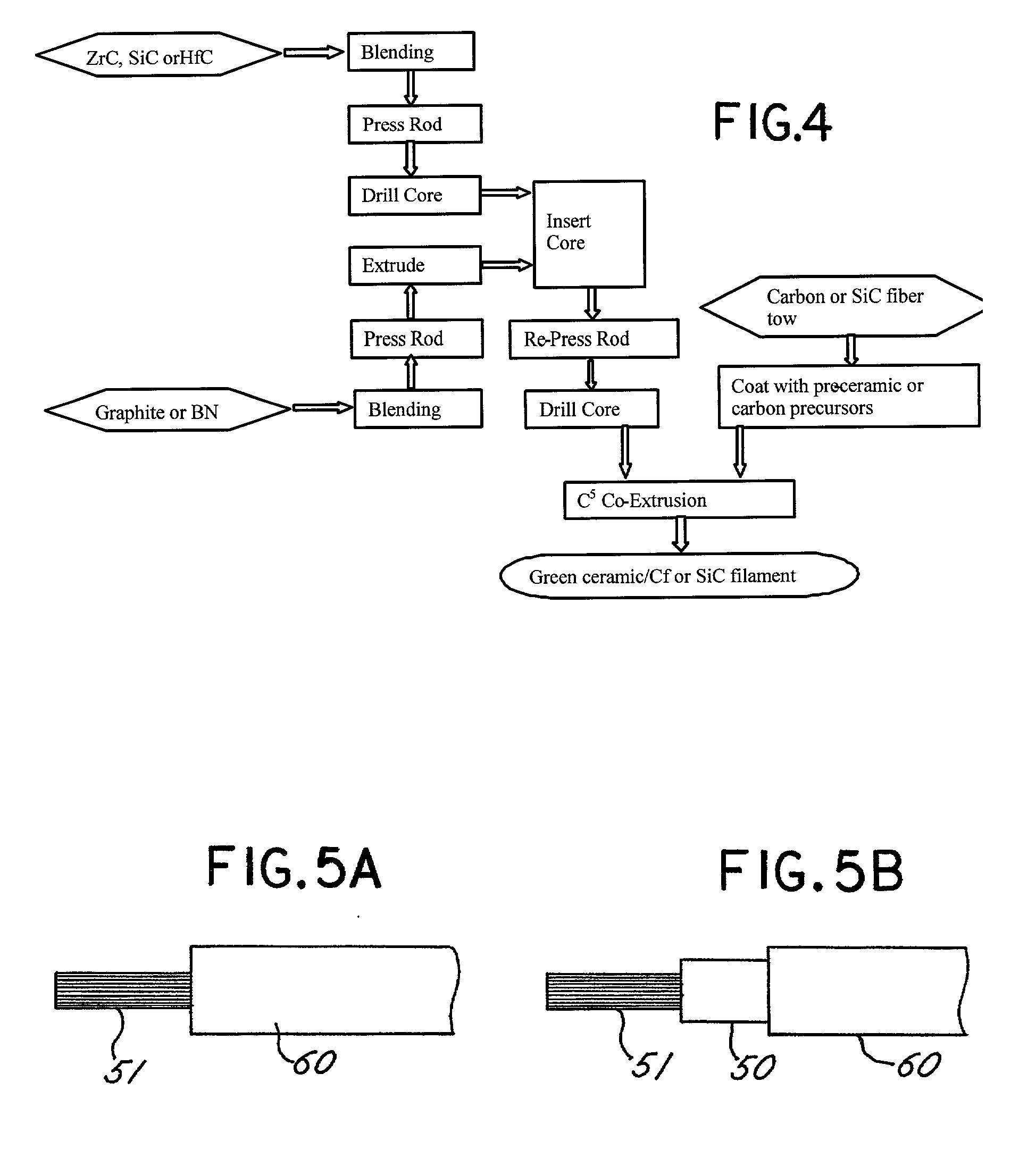
[0086] In the above-cited formulation of Table 3, HfC is hafnium carbide powder from Cerac, Inc., designated as H-1004, B-67 is acryloid resin from Rohm and Haas, EEA is ethylene-ethyl acetate copolymers, and HMO is heavy mineral oil which is a plasticizer. A "Brabender" mixing machine (from C. W. Brabender of South Hackensack, N.J.) was used to mix the above-cited materials. The mixture of materials can then be formed into a feed rod with a hole through the symmetrical axis of the feed rod. After mixing, the mixture was formed into a feed rod-like shape like that...

example 2

Hafnium Carbide Matrix / Graphite Interface / Carbon Fiber Reinforcement

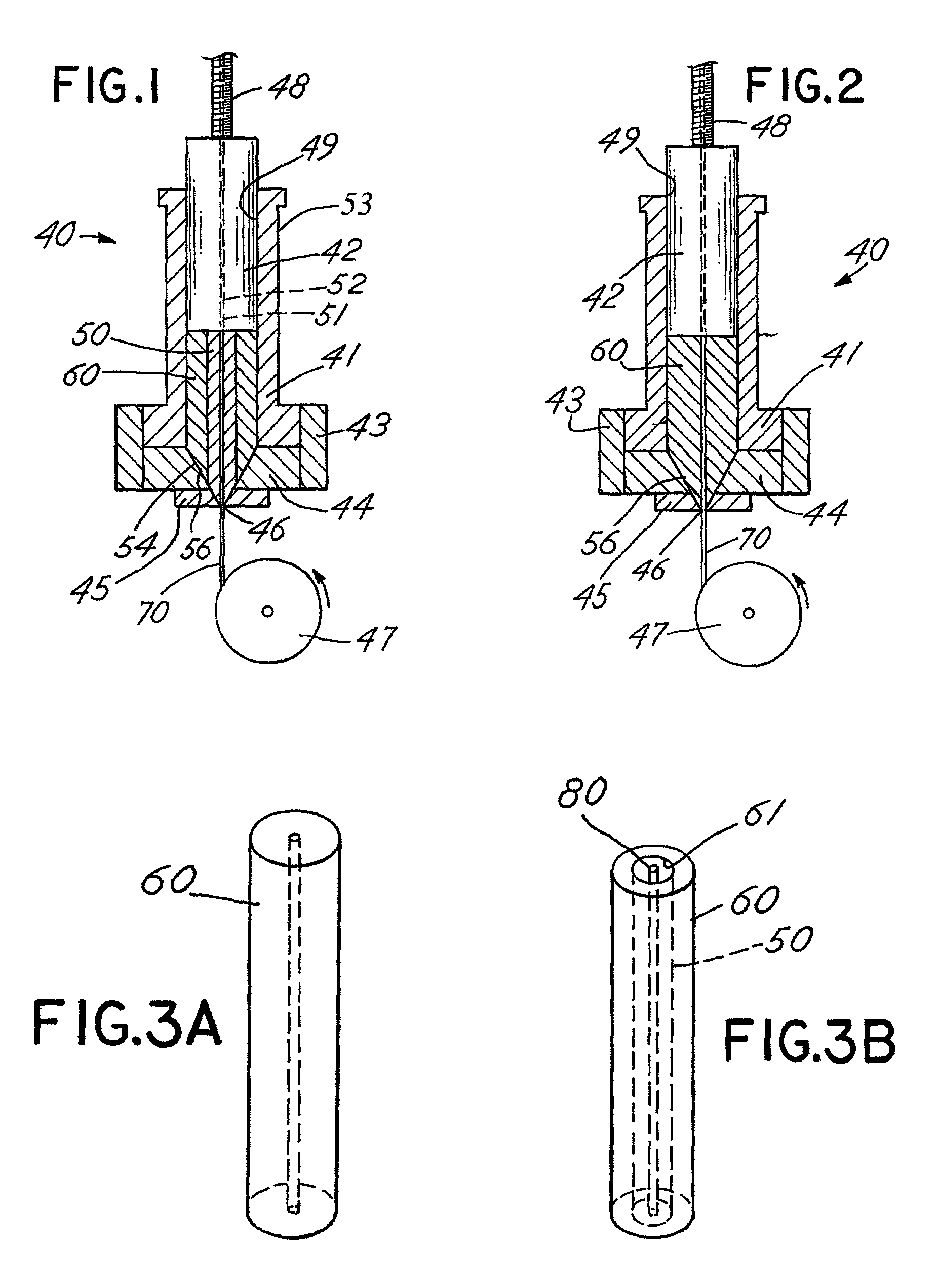
[0087] The hafnium carbide matrix made in accordance with Example 1 is the same matrix for Example 2. The only difference in Example 2 is that the hole through the symmetrical axis of the feed rod is made larger so that a graphite interface can be inserted through the hole of the feed rod. The graphite interface defines a hole through its symmetrical axis, and the carbon fiber reinforcement can be inserted into the hole of the graphite interface, resulting in the product illustrated in FIG. 3B. Following coextrusion, desired formation (such as a billet), lamination, pyrolysis, and firing as described in Example 1 and 2 the result is a fully dense composite formation. The formulation for the graphite interface is as follows.

[0088] VPCA-BRO6

[0089] Description: Core Material

[0090] Brabender Size: small

[0091] Batch Size: 42 cc

[0092] Batch Temperature: 150.degree. C.

[0093] Batch Speed: 60 rpm

[0094] Ingredients:

4TABLE 4 M...

example 3

[0097] The present invention can be used to make other reinforcements, including but not limited to:

[0098] Zirconium Carbide Matrix / Graphite Interface / Carbon Fiber Reinforcement;

[0099] Zirconium Carbide Matrix / No Interface / Carbon Fiber Reinforcement or Silicon Carbide Reinforcement;

[0100] Silicon Carbide Matrix / No Interface / Carbon Fiber Reinforcement;

[0101] Hafnium Diboride Matrix / Graphite Interface / Carbon Fiber Reinforcement;

[0102] Silicon Carbide Matrix / Boron Nitride Interface / Silicon Carbide Reinforcement;

[0103] Silicon Nitride Matrix / Boron Nitride Interface / Silicon Carbide Reinforcement;

[0104] Silicon Carbide Matrix / Boron Nitride-Sodium Silicate Interface / Carbon Fiber Reinforcement;

[0105] Silicon Carbide Matrix / Carbon-Silicon Carbide Interface doped with boron / Carbon Fiber Reinforcement;

[0106] Silicon Carbide Matrix / Carbon-Silicon Carbide-Sodium Silicate Interface doped with boron / Silicon Carbide Fiber Reinforcement;

[0107] Silicon Carbide Matrix / Boron Nitride-Sodium Silicate Int...


PUM

PropertyMeasurementUnit
Percent by volumeaaaaaaaaaa
Temperatureaaaaaaaaaa
Volumeaaaaaaaaaa

Abstract

A process for continuous composite coextrusion comprising: (a) forming first a material-laden composition comprising a thermoplastic polymer and at least about 40 volume % of a ceramic or metallic particulate in a manner such that the composition has a substantially cylindrical geometry and thus can be used as a substantially cylindrical feed rod; (b) forming a hole down the symmetrical axis of the feed rod; (c) inserting the start of a continuous spool of ceramic fiber, metal fiber or carbon fiber through the hole in the feed rod; (d) extruding the feed rod and spool simultaneously to form a continuous filament consisting of a green matrix material completely surrounding a dense fiber reinforcement and said filament having an average diameter that is less than the average diameter of the feed rod; and (e) depositing the continuous filament into a desired architecture which preferably is determined from specific loading conditions of the desired object and CAD design of the object to provide a green fiber reinforced composite object.

Description

[0001] This application is based on, and claims the benefit of, co-pending U.S. Provisional Application Serial No. 60 / 259,284, filed on Jan. 2, 2001, and entitled "Automated Tow Placement Process for Fabricating Fiber Reinforced Ceramic Matrix Composites".[0003] The present invention relates to continuous composite coextrusion methods, apparatuses for coextrusion, and compositions for preparing composites, such as continuous fiber reinforced ceramic matrix composites, using dense fibers and green matrices as well as to methods and apparatuses for the preparation of composites having interfaces between dense fibers and green matrices, particularly three-dimensional objects having complex geometries.[0004] BACKGROUND OF THE INVENTION[0005] Composites are combinations of two or more materials present as separate phases and combined to form desired structures so as to take advantage of certain desirable properties of each component. The materials can be organic, inorganic, or metallic, ...

Claims


Application Information

Patent Timeline
IPC IPC(8): B29B15/12B29C48/475B29C70/02B29C70/38B32B5/26C04B35/628C04B35/80G05B19/4099
CPCB29B15/122B29C47/0014B29C47/0021B29C47/54B29C70/025B29C70/382B32B5/26C04B35/5622C04B35/565C04B35/58078C04B35/584C04B35/62625C04B35/6263C04B35/62849C04B35/62857C04B35/6286C04B35/62863C04B35/62868C04B35/62871C04B35/62873C04B35/63C04B35/6303C04B35/634C04B35/806C04B2235/3217C04B2235/3804C04B2235/3813C04B2235/3826C04B2235/3839C04B2235/422C04B2235/48C04B2235/524C04B2235/5244C04B2235/5248C04B2235/5264C04B2235/5436C04B2235/6026C04B2235/80G05B19/4099G05B2219/49015B33Y10/00B33Y30/00B29C64/165B29C48/05B29C48/08B29C48/475Y10T428/24994Y10T442/2123C04B35/80Y02P90/02B32B37/153
Inventor VAIDYANATHAN, K. RANJIWALISH, JOSEPHFOX, MARKGILLESPIE, JOHN W. JR.YARLAGADDA, SHRIDHAREFFINGER, MICHAEL R.MULLIGAN, ANTHONY C.RIGALI, MARK J.
Owner ADVANCED CERAMICS
Why Eureka
Try Eureka