Method for pulling single crystal

a single crystal and crystal technology, applied in the direction of polycrystalline material growth, crystal growth process, polycrystalline material growth, etc., can solve the problems of high strength for supporting the single crystal ingot, the apparatus for pulling up the single crystal to be damaged, and the difficulty of producing the dislocation-free single crystal

Inactive Publication Date: 2003-03-13
SUMITOMO MITSUBISHI SILICON CORP
View PDF0 Cites 8 Cited by
  • Summary
  • Abstract
  • Description
  • Claims
  • Application Information

AI Technical Summary

Benefits of technology

0047] The function and advantage of the present invention will be described, based on the present examples 1 and 2 and the comparative examples 1 and 2.

Problems solved by technology

When, however, the diameter at the neck portion exceeds 5 mm, the dislocations can hardly be moved to the outside the crystal, thereby making it difficult to produce the dislocation-free single crystal.
However, if the diameter at the neck portion is set to be too small, a high strength for supporting the single crystal ingot cannot be obtained.
As a result, a fracture takes place at the neck portion in the process of pulling up the crystal or in the subsequent processes of cooling and removing the ingot, and further there is a possibility that the single crystal drops into the molten material in the crucible, thereby causing the apparatus for pulling up the single crystal to be damaged, the overflow of the molten material, steam explosion and other effects to take place, and causing a possible accident resulting in injury.
However, even if the diameter at the neck portion is controlled into a fixed value, the crystal shape at the neck is altered when an unexpected disturbance occurs in the temperature of the molten material in the crucible.
If the diameter of the single crystal at the neck portion is increased so as to avoid the above-mentioned problem, it is difficult to eliminate dislocations from the single crystal in the Dash neck method, as described above, so that the work to re-form the neck portion is frequently repeated.
Along with an increase in the weight of the single crystal, when it is preferentially intended to prevent the neck portion from being damaged or to prevent the single crystal from dropping, it is difficult to eliminate dislocations therefrom, thereby increasing the number of the re-works in the Dash neck process and thus reducing the efficiency conspicuously in the process of the single crystal.
Actually, when a single crystal having a diameter of 3 to 4 mm as a target diameter is produced with the conventional Dash neck process, a sudden change in the temperature of the molten material makes it difficult to control the diameter at the neck portion, and a single crystal having a smaller diameter compared with a preset target value is usually formed.

Method used


Image

  • Method for pulling single crystal
  • Method for pulling single crystal
  • Method for pulling single crystal

Examples


example 1

Present Example 1

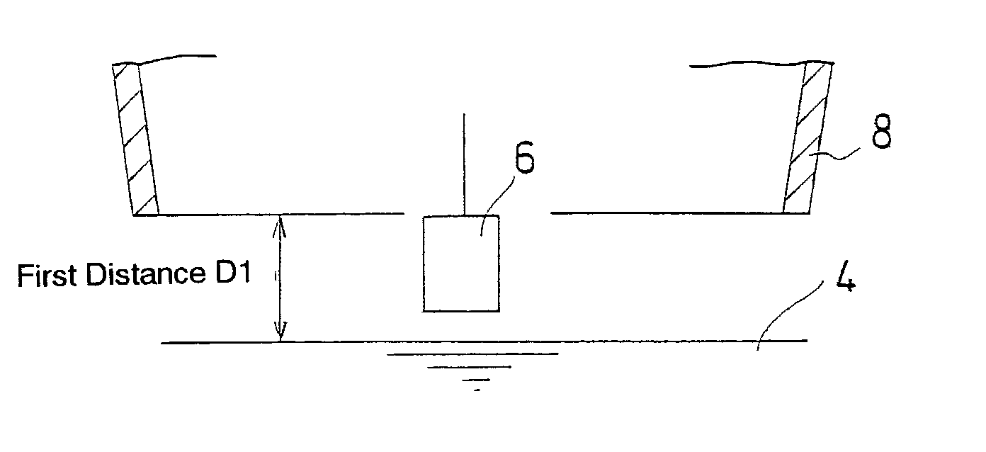
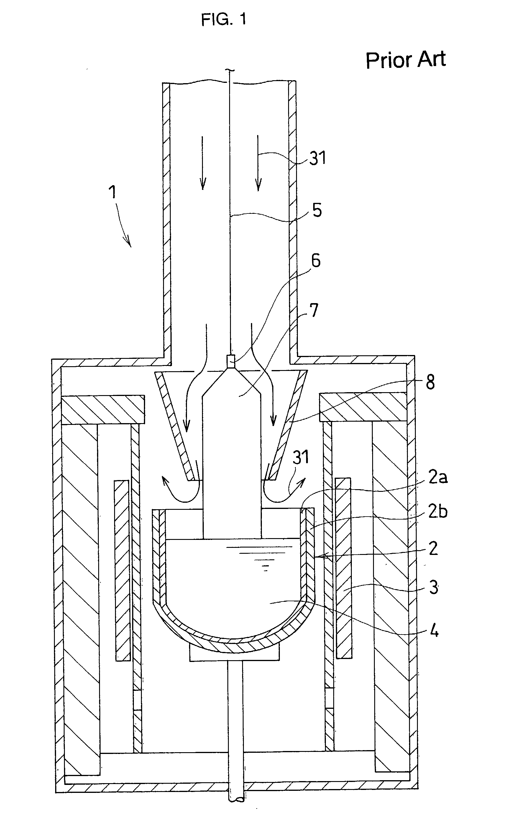
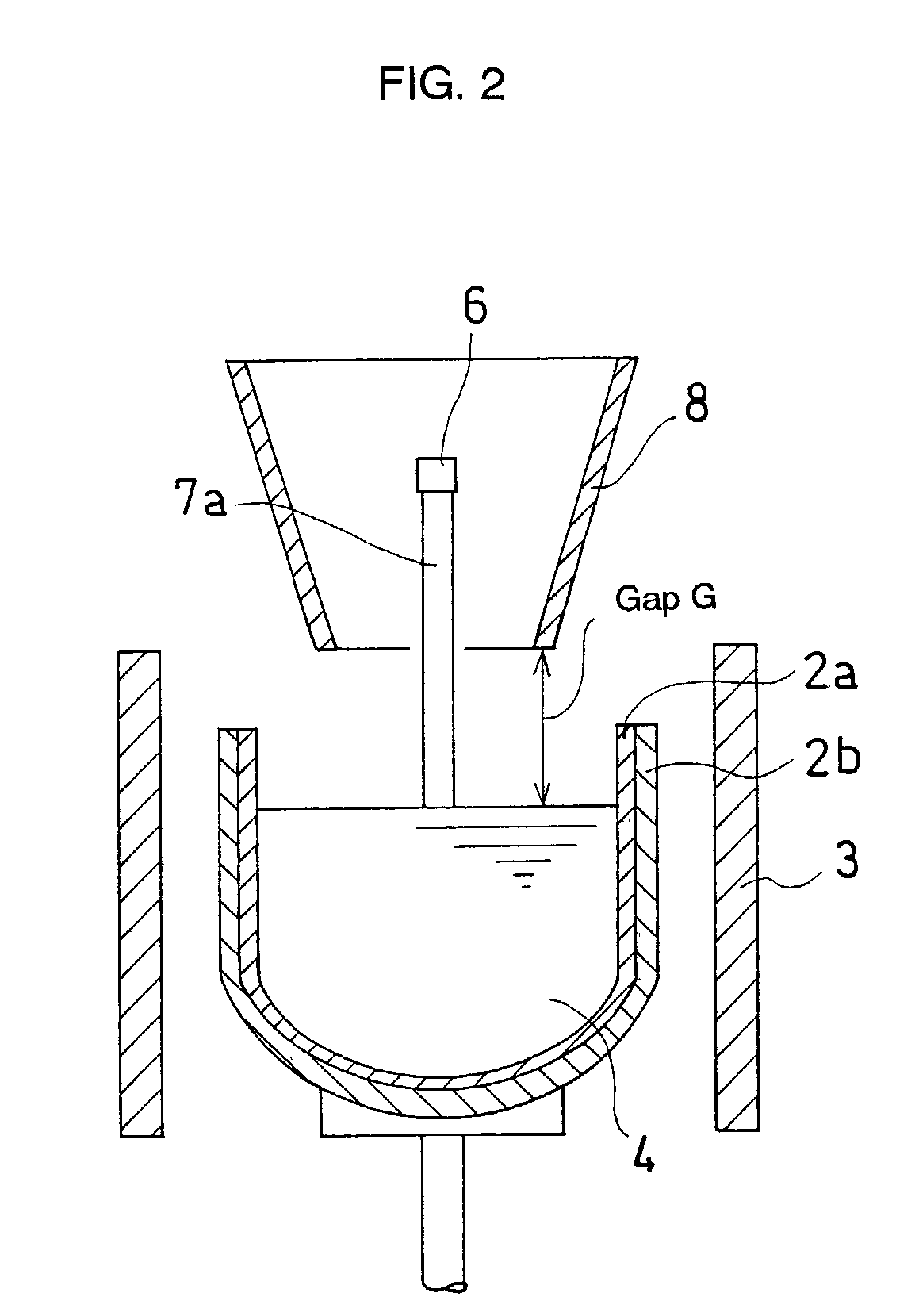
[0048] Using the single crystal producing apparatus shown in FIG. 1, a single crystal having a heavy weight of 200 Kg and a 300 mm diameter and a 1000 mm body length in the finished shape was pulled. The crystal was grown as follows: the material having a charge amount of 220 Kg was pulled up at a rate of 2.5 mm / min to form a single crystal having a target diameter of 6 mm at the neck portion under the conditions that the revolution speed of the crystal was 6 r.p.m.; the revolution speed of the crucible was 12 r.p.m.; and the gap was set to be a first distance D1 of 100 mm. Thereafter, the gap was altered to a second distance D2 of 30 mm at a gap-changing speed of 0.7 mm / min and the crystal was pulled to form a single crystal at the shoulder portion and subsequently pulled up at a rate of 0.7 mm / min to form a single crystal having the target diameter of 300 mm at the body portion. Thus, 10 single crystals were produced under the same conditions.

[0049] FIG. 4 is a di...

example 2

Present Example 2

[0050] A single crystal at the neck portion was grown under the same conditions as in the present example 1, except for a first distance D1 of 120 mm being used. After that, the gap was changed into a second distance D2 of 30 mm at a changing speed of 0.7 mm / min, and the crystal was further grown at the shoulder portion and subsequently at the body portion. Thus, 10 single crystals were produced under the conditions.


PUM

PropertyMeasurementUnit
distanceaaaaaaaaaa
distanceaaaaaaaaaa
lengthaaaaaaaaaa

Abstract

A method capable of securely pulling up a heavy single crystal is described. Using an apparatus comprising a crucible for storing a molten material for a single crystal; a heater for heating the molten material; means for pulling up the single crystal to grow by bringing a seed crystal in contact with the surface of the molten material in the crucible; and a flow-regulating member surrounding the single crystal at the growth area for shielding the heat of radiation and for regulating inert gas flow, the method comprises the following steps of: setting the distance between the lower end of the flow-regulating member and the surface of the molten material to be a first distance D1 when the seed crystal comes into contact with the surface of the molten material in said crucible; forming the single crystal at the neck portion; thereafter setting the distance between the lower end of the flow-regulating member and the surface of the molten material to be a second distance D2 where D1 (mm)>D2 (mm); and forming the single crystal at the shoulder portion and subsequently forming the single crystal at the body portion. A dislocation-free single crystal having a heavy weight can be produced with a high crystal quality, and the method is applicable to various operation modes at which the apparatus is operated under various conditions of crystal growth.

Description

[0001] The present invention relates to a method for pulling up a single crystal of semiconductor, such as silicon or the like, and more specifically to a method for pulling up a single crystal having a heavy weight, in which case, the single crystal can be grown in the dislocation-free state without any accidents of the single crystal dropping, thereby ensuring to stably produce the single crystal in a high crystalline quality.DESCRIPTION OF THE PRIOR ART[0002] In recent years, silicon single crystals, which are used to form a circuit device, such as a large-scale integrated circuit (LSI's), have been mostly produced by means of the Czochralski method (hereafter referred to as "the CZ method"). Such a single crystal grown by the CZ method is usually pulled up from a molten material in a quartz crucible, and oxygen is included in the crystal. This provides excellent properties regarding the substrate quality in the process of manufacturing LSI's.[0003] In producing a single crystal ...

Claims


Application Information

Patent Timeline
Patent Type & Authority Applications(United States)
IPC IPC(8): C30B15/00C30B15/14C30B29/06
CPCC30B15/14C30B15/203C30B29/06Y10T117/1068Y10T117/1088Y10T117/1072Y10T117/1032
Inventor MORITA, HIROSHIWATANABE, HIDEKI
Owner SUMITOMO MITSUBISHI SILICON CORP
Why Eureka
Try Eureka