
Organic electrolysis reactor for performing an electrolytic oxidation reaction and method for producing a chemical compound by using the same

an electrolysis reaction and electrolysis reactor technology, applied in the field of electrolysis reaction reactors, can solve the problems of low selectivity for and yield of desired compounds, large amount of energy consumed, explosions,

Inactive Publication Date: 2003-04-17
ASAHI KASEI KK
View PDF0 Cites 27 Cited by
  • Summary
  • Abstract
  • Description
  • Claims
  • Application Information

AI Technical Summary

Problems solved by technology

However, the carbonylation reactions frequently pose problems, for example, in that a lowering of a catalyst activity occurs, that a corrosion of a reactor occurs due to the formation of a corrosive by-product derived from a catalyst, that a large amount of energy is consumed due to the use of high reaction temperature and high reaction pressure, that a danger of explosion is present due to the occurrence of a mixing of a starting material with oxygen or a mixing of a reaction product with oxygen, and that the selectivity for and yield of a desired compound are low.
However, the method (I) is disadvantageous from the viewpoint of safety, since the method (I) has a great defect in that it is necessary to use phosgene (which is poisonous) as a raw material.
Further, the method (I) poses a problem that hydrogen chloride (which is highly corrosive) is by-produced during the reaction.
Also, the cost of these methods has reached a level which can compete with the cost of the phosgene method.
However, these methods (II) to (IV) still have many problems.
For example, the method (II) has the problem that a corrosion of a reactor occurs due to a by-produced, chlorine-containing compound.
Therefore, in this method, it is necessary for the inside of the reactor to have a glass lining or an enamel lining, so that it becomes difficult to increase the size of the reactor.
However, in this method, carbon dioxide is by-produced, and the by-produced carbon dioxide must be purged from the reaction system, and the purging of carbon dioxide inevitably causes a large loss of carbon monoxide and, hence, a lowering of the carbon monoxide partial pressure.
Therefore, it becomes difficult to achieve a satisfactory reaction rate.
Therefore, this method has a defect in that it is necessary to perform additional steps for separating the produced carbonic diester from the solids by, for example, membrane separation or centrifugation separation.
However, this method has a problem in that a copper compound as an auxiliary catalyst is converted to a copper oxide, which is precipitated, and, also, by-produced water (by-produced when a carbonic diester is formed) converts the above-mentioned copper compound to a basic copper chloride, which is precipitated, so that it becomes difficult to produce a carbonic diester continuously and stably.
However, the method (IV) has problems in that the catalyst activity becomes unsatisfactory, and that the catalyst activity becomes unstable since an insoluble metal compound, such as a basic copper chloride, is precipitated on the solid catalyst due to the presence of water which is by-produced.
Thus, with this method, a carbonic diester cannot be produced stably and in high yield for a long time.
Further, the method (IV) uses a mixture of an alcohol, which is flammable, carbon monoxide and oxygen, and such a mixture is explosive, posing a problem from the viewpoint of safety.
As mentioned above, the carbonylation reaction is thermodynamically disadvantageous, but can be performed relatively easily by utilizing an electrolysis.
However, the method (V) above has a problem in that, for obtaining a carbonic diester in high yield and with high current efficiency, the reaction needs to be performed under a carbon monoxide pressure as high as 100 atm., so that the use of a reactor which can stand very high pressure is needed, and it is necessary to perform circulation of a high pressure gas.
Therefore, this method is unsuitable for commercial practice.
However, this method has a defect in that the selectivity for and yield of the carbonic diester obtained are low.
As apparent from the above, no method has conventionally been proposed which can be used for producing various compounds (e.g., a carbonic diester) efficiently, stably and safely by an electrolytic oxidation reaction (e.g., an electrolytic carbonylation reaction).
Also, no reactor has conventionally been proposed which can exhibit an excellent performance when used for producing a compound by an electrolytic oxidation reaction.

Method used


Image

  • Organic electrolysis reactor for performing an electrolytic oxidation reaction and method for producing a chemical compound by using the same
  • Organic electrolysis reactor for performing an electrolytic oxidation reaction and method for producing a chemical compound by using the same
  • Organic electrolysis reactor for performing an electrolytic oxidation reaction and method for producing a chemical compound by using the same

Examples


examples 2 and 3

[0251] The same procedure as in Example 1 was repeated except that a voltage of 1.7 V (Example 2) or 5.0 V (Example 3) was applied between the anode and the cathode. The results are shown in Table 1.

examples 4 to 15

[0252] The same procedure as in Example 1 was repeated except that, in stead of phosphoric acid, the below-mentioned electrolytes were individually used in the concentrations shown in Table 1: tetramethyl ammonium bromide, tetraethyl ammonium bromide, tetrapropyl ammonium bromide, tetrabutyl ammonium bromide, tetrahexyl ammonium bromide, tetraethyl ammonium perchlorate, tetrapropyl ammonium perchlorate, tetrabutyl ammonium perchlorate, ammonium perchlorate, and sodium perchlorate. The results are shown in Table 1.

example 16

[0253] The same procedure as in Example 13 was repeated except that the amount of palladium chloride was changed to 0.6 mg. The results are shown in Table 1.

2TABLE 1 Quan- Cur- tity rent of Elec- Concen- Voltage effi- elec-Example tro-tration applied Products (.mu.mol) ciency tricity No. lyte (M) (V) DMC OxDM DMM MF (%) (C) 1 H.sub.3PO.sub.4 1.1 3.5 18.2 1.2 0.4 1.6 58.5 6.0 2 H.sub.3PO.sub.4 1.1 1.7 4.0 0.3 0.5 1.9 43.1 1.8 3 H.sub.3PO.sub.4 1.1 5.0 20.9 2.4 0.4 1.5 47.1 8.6 4 Me.sub.4NBr 0.05 3.5 46.7 0.2 2.5 5.7 45.2 19.9 5 Et.sub.4NBr 0.05 3.5 52.2 0 2.2 6.7 47.5 21.2 6 Pr.sub.4NBr 0.05 3.5 32.6 0 1.8 7.1 38.5 16.3 7 Bu.sub.4NBr 0.05 3.5 42.7 0 2.0 6.2 45.7 18.0 8 Hx.sub.4NBr 0.05 3.5 33.2 0 1.7 3.4 42.4 15.1 9 Et.sub.4NClO.sub.4 0.05 3.5 62.0 6.9 2.3 3.0 61.4 19.5 10 Pr.sub.4NClO.sub.4 0.05 3.5 46.3 11.7 3.0 2.4 52.1 17.1 11 Bu.sub.4NClO.sub.4 0.05 3.5 51.1 2.4 1.7 2.2 58.5 16.9 12 NH.sub.4ClO.sub.4 0.05 3.5 69.2 24.5 2.5 2.7 59.1 22.6 13 NaClO.sub.4 0.05 3.5 62.6 10.1 2.2 3.2 ...


PUM


Abstract

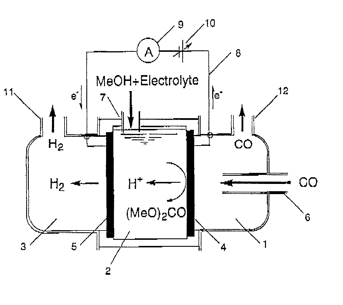
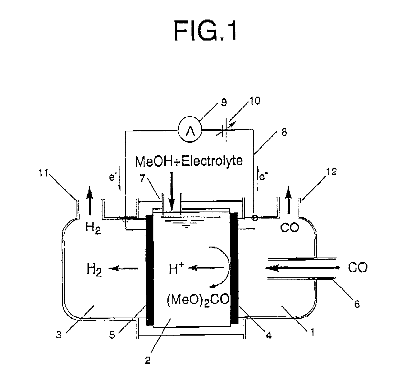
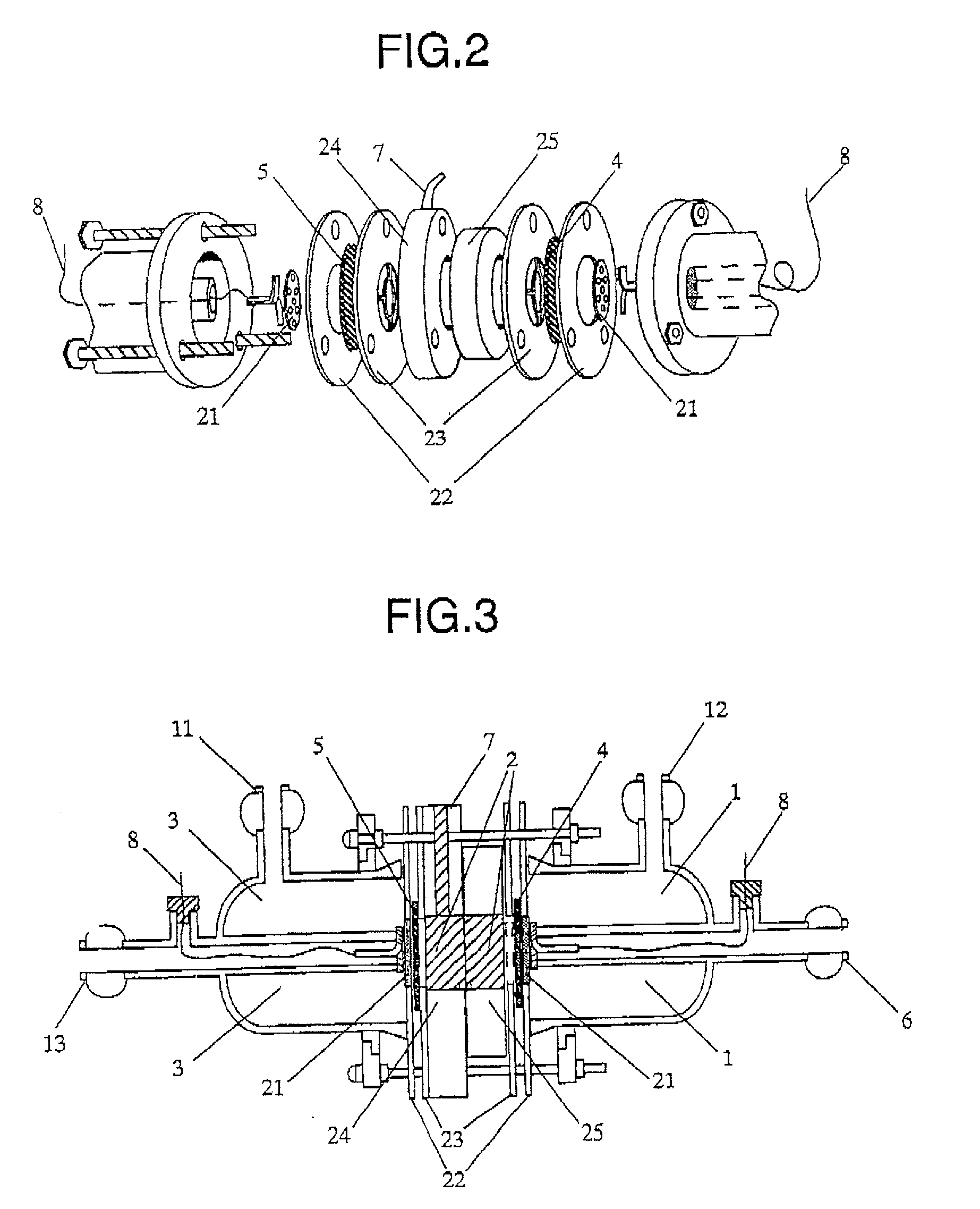
Disclosed is an organic electrolysis reactor for performing an electrolytic oxidation reaction of a system comprising a substrate and a reductant, comprising: a casing; an anode which comprises an anode active material and which is ion-conductive or active species-conductive; a cathode which comprises a cathode active material and which is ion-conductive or active species-conductive; and means for applying a voltage between the anode and the cathode, wherein the means for applying a voltage is disposed in the outside of the casing and connected to the anode and the cathode, wherein the anode and the cathode are disposed in spaced relationship in the casing to partition the inside of the casing into an intermediate compartment between the anode and the cathode, and an anode compartment on the outside of the anode. Also disclosed is a method for producing a chemical compound by performing an electrolytic oxidation reaction of a system comprising a substrate and a reductant, using the organic electrolysis reactor mentioned above.

Description

[0001] 1. Field of the Invention[0002] The present invention relates to an organic electrolysis reactor for performing an electrolytic oxidation reaction. More particularly, the present invention is concerned with an organic electrolysis reactor for performing an electrolytic oxidation reaction of a system comprising a substrate and a reductant, comprising: a casing; an anode which comprises an anode active material and which is ion-conductive or active species-conductive; a cathode which comprises a cathode active material and which is ion-conductive or active species-conductive; and means for applying a voltage between the anode and the cathode, wherein the means for applying a voltage is disposed in the outside of the casing and connected to the anode and the cathode, wherein the anode and the cathode are disposed in spaced relationship in the casing to partition the inside of the casing into an intermediate compartment between the anode and the cathode, and an anode compartment ...

Claims


Application Information

Patent Timeline
IPC IPC(8): C25B1/02C25B3/23H01M8/10
CPCC25B1/02C25B3/02Y02E60/522Y02E60/523H01M8/10Y02P70/50Y02E60/50C25B3/23
Inventor OTSUKA, KIYOSHIYAMANAKA, ICHIROSUZUKI, KEN
Owner ASAHI KASEI KK
Learn More