Method for the preparation of a lithographic printing plate

a technology of lithographic printing and printing plate, which is applied in the field of method for the preparation of lithographic printing plate, can solve the problems of large number of new computer-to-plate system, large number of large-scale computer-to-plate system, and high cos

Inactive Publication Date: 2003-05-15
AGFA NV
View PDF6 Cites 18 Cited by
  • Summary
  • Abstract
  • Description
  • Claims
  • Application Information

AI Technical Summary

Benefits of technology

0030] It is an object of the present invention to provide a method for the preparation of a lithographic printing plate whereby the plate can be developed by fountain and / or ink on press, so that no separate processing equipment or chemicals are required.

Problems solved by technology

A disadvantage of this traditional method is the necessary cumbersome preparation of the photographic intermediate film involving wet processing.
A further drawback is the wet processing of the printing plate itself.
Many of the new computer-to-plate system are large, complex, and expensive.
Solid ink jet printing has serious disadvantages for lithographic plates in that the wax or resin image has limited durability due to its thermoplastic, chemical, and adhesive properties and the amount and rounded shape of the solidified ink jet droplet on the media do not have the intrinsic image resolution properties found in liquid ink jet printing.
Thus this approach adds to the complexity and expense of the platemaking process and does not depend on the ink jet ink image for the hydrophobic image of the plate.
As a result, the resolution of the printed images at shadow area or reversed lines is not so good.
Moreover, a large amount of ink is needed in this method because the ink-repelling material must be deposited on the whole non-image part which occupies most of the surface of the printing plate, thereby delaying the printing process.
This is an obnoxious method due to the sometimes high vapour pressure and toxicity of said inks.
The printing endurance of said printing plates is low.
Therefore, even the use of an ink composition having a very high surface tension results in a poor image on the surface of the substrate because of ink spreading and low printing endurance.
This is an uneconomical and cumbersome method.
However said printing plates have a bad ink acceptance and a low printing endurance.
There is not indicated how said inks are made but from the examples it is clear that it concerns artificial latices, which are difficult to prepare.
This is a cumbersome process.
The lithographic printing plate precursors based on heat mode according to the above cited references show the drawback that they require a complicated and expensive platesetter apparatus equipped with an an expensive and short-living high power IR exposure unit.
Furtheron their working mode is limited to positive working.
A disadvantage of this system and of most systems disclosed in the references cited above is the need for a processing off press, so that separate processing equipment and chemicals are required.

Method used


Image

  • Method for the preparation of a lithographic printing plate
  • Method for the preparation of a lithographic printing plate
  • Method for the preparation of a lithographic printing plate

Examples


example 1

[0103] Preparation of the Printing Plate Precursor

[0104] A 0.30 mm thick aluminum foil was degreased by immersing the foil in an aqueous solution containing 5 g / l of sodium hydroxide at 50.degree. C. and rinsed with demineralized water. The foil was then electrochemically grained using an alternating current in an aqueous solution containing 4 g / l of hydrochloric acid, 4 g / l of hydroboric acid and 5 g / l of aluminum ions at a temperature of 35.degree. C. and a current density of 1200 A / m.sup.2 to form a surface topography with an average center-line roughness Ra of 0.5 mm.

[0105] After rinsing with demineralized water the aluminum foil was then etched with an aqueous solution containing 300 g / l of sulphuric acid at 60.degree. C. for 180 seconds and rinsed with demineralized water at 25.degree. C. for 30 seconds.

[0106] The foil was subsequently subjected to anodic oxidation in an aqueous solution containing 200 g / l of sulphuric acid at a temperature of 45.degree. C., a voltage of about...

example 2

[0115] Preparation of the Printing Plate Precursor

[0116] The following coating composition was coated on the lithographic support described in example 1 at a wet coverage of 30 g / m.sup.2, and dried at 35.degree. C.

[0117] Preparation of the coating composition:

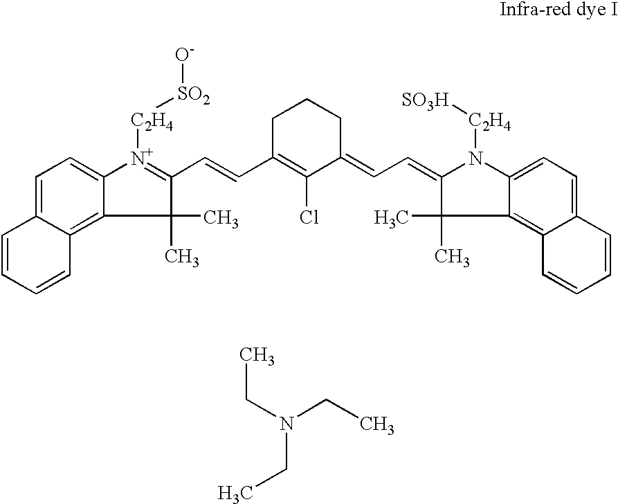
[0118] To 7.5 g of a 20% w / w dispersion of polystyrene (particle diameter of 60 nm) stabilized with a surfactant (1.5% w / w vs. polymer) in deionized water was added 20 g of a 1% w / w solution of infra-red dye I (see formula below).

[0119] To the above obtained solution was added 66.5 g deionized water and 6 g of a 5% w / w solution of CARBOPOL WS801 (polyacrylic acid commercially available from Goodrich). 2

[0120] Preparation of the Fluid

[0121] The fluid was prepared by dissolving 8 g of A-1 in a mixture of 90 g of water and 10 g of isopropanol. After filtering the solution was loaded into the ink cartridge of an Epson Stylus Color 900 ink-jet printer, the cartridge having previously been emptied and cleaned.

[0122] A test pattern co...

examples 3 to 12

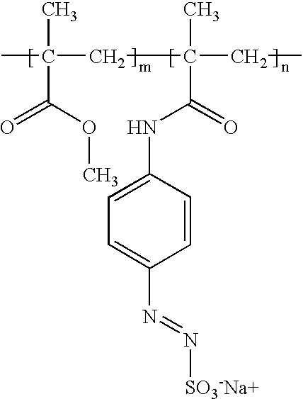
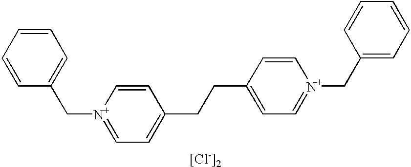
[0124] The insolubilizing capacity of several insolubilizing compounds (see formulas below) was tested using the following procedure.

[0125] The insolubilizing compound was dissolved in a solvent carrier at a concentration of 1%. Next a 6 .mu.l droplet of each fluid was jetted on the printing plate precursor as defined in example 1. The droplet was dried at room temperature to remove the solvent carrier of the fluid. Next the plate was mounted on the press and the printing procedure as described in example 1 was used.

[0126] If the droplet-area of the image forming layer is ink-accepting, the compound is suitable for use in this invention.

2 Droplet-area remains on the lithographic support and Example Compound accepts ink 3 Flexo Blue 630 Yes 4 Crystal Violet Yes 5 Acridine Orange Base Yes 6 A-1 Yes 7 A-2 Yes 8 A-3 Yes 9 A-4 Yes 10 A-5 Yes 11 A-6 Yes 12 A-7 Yes Formulas of compounds A-1 to A-7 A-1 3 A-2 4 A-3 5 A-4 6 A-5 7 A-6 8 A-7 9


PUM

PropertyMeasurementUnit
temperatureaaaaaaaaaa
particle sizeaaaaaaaaaa

Abstract

A method for the preparation of a negative working lithographic printing plate is disclosed. A printing plate precursor comprising a lithographic support and an image forming layer is mounted on a printing press. A liquid containing a dissolution inhibitor is image-wise dispensed on the precursor by means of ink jet printing. The precursor is developed on press by the application of fountain and ink whereby the image areas are retained and the non-image areas are removed.

Description

[0001] The present invention relates to the preparation of a lithographic printing plate by means of direct ink jet printing.[0002] Traditional techniques of printing include letterpress printing, gravure printing and offset lithography. All of these printing methods require a plate, usually loaded onto a plate cylinder of a rotary press for efficiency, to transfer ink in the pattern of the image. In letterpress printing, the image pattern is represented on the plate in the form of raised areas that accept ink and transfer it onto the recording medium by impression. Gravure printing cylinders, in contrast, contain series of wells or indentations that accept ink for deposit onto the recording medium.[0003] In the case of traditional offset lithography the image to be printed is present on a plate as a pattern of ink accepting (oleophilic) areas on an ink repellent (oleophobic or hydrophilic) background. In the wet system the required ink repellency is provided by an initial applicati...

Claims


Application Information

Patent Timeline
Patent Type & Authority Applications(United States)
IPC IPC(8): B41C1/10
CPCB41C1/1066
Inventor DAMME, MARC VANLOCCUFIER, JOHAN
Owner AGFA NV
Why Eureka
Try Eureka