Plasma CVD apparatus conducting self-cleaning and method of self-cleaning

a self-cleaning and plasma technology, applied in chemical vapor deposition coatings, chemical apparatus and processes, coatings, etc., can solve problems such as the formation of unwanted by-products (aluminum fluoride,

Inactive Publication Date: 2003-05-29
ASM JAPAN
View PDF35 Cites 101 Cited by
  • Summary
  • Abstract
  • Description
  • Claims
  • Application Information

AI Technical Summary

Problems solved by technology

The deposits then adhere onto substrates as foreign objects and cause impurity contamination, which results in defects.
As a result, unwanted by-products (for example, aluminum fluoride if electrodes are made of an aluminum alloy) are formed.
Because the by-products float, or surface layers of the electrode surface attacked by ion bombardment are exfoliated and fall on the substrate, impurity contamination is caused.
Because such maintenance work is required, an apparatus throughput declines and operation cost increases.
As a result, the throughput of the apparatus declines.
However, the present inventors believe that the above invention has the following disadvantages: First, when temperature-controlled ceramic liners are used, resistance-heating heater wires for heating are required to be installed inside the ceramic liners and the costs of this are commercially high.
Heat transfer via a gas or radiation heating is not sufficient to heat the showerhead to 200.degree. C. or higher.
The greater the showerhead surface, the higher the cleaning rate becomes, but the worse the evenness of a film becomes.
Although this cleaning cycle depends on the type of film deposited and roughness of the showerhead surface and other factors, in either situation, when the temperature of the showerhead rises, it can be said that film density increases, adherence increases and it becomes difficult for the film to exfoliate.
It is thought that a cause for a particularly slow cleaning rate of the periphery of the showerhead surface is that a large amount of film with high density adheres to this area.
It is thought that a cause for a particularly slower rate of cleaning the periphery of the showerhead surface is because a great amount of dense film with high density adheres to this area.

Method used


Image

  • Plasma CVD apparatus conducting self-cleaning and method of self-cleaning
  • Plasma CVD apparatus conducting self-cleaning and method of self-cleaning
  • Plasma CVD apparatus conducting self-cleaning and method of self-cleaning

Examples


embodiment 2

[0092] FIG. 6 shows Embodiment 2 of the capacitive coupled plasma CVD apparatus for conducting self cleaning according to the present invention. This apparatus is a capacitive coupled plasma CVD apparatus for conducting remote plasma cleaning to process 300 mm substrates.

[0093] Inside a reactor, a susceptor 603 for placing an object-to-be-processed 601 such as glass or silicon substrates on it is set up. The susceptor 603 comprises preferably ceramic or aluminum alloy, inside which a resistance-heating heater is embedded. The susceptor 603 is also used as a lower electrode for generating a plasma. In this embodiment, the susceptor 603 has a diameter of 325 mm and an area 1.17 times larger than that of an object-to-be-processed 601 with a diameter of .O slashed.300 mm. Within the range of 1.08 to 1.38 times, a susceptor of a different diameter can be used. A showerhead 604 for emitting reaction gases equally to the object-to-be-processed 601 is set up on the ceiling of the reactor an...

embodiment

[0104] Embodiment

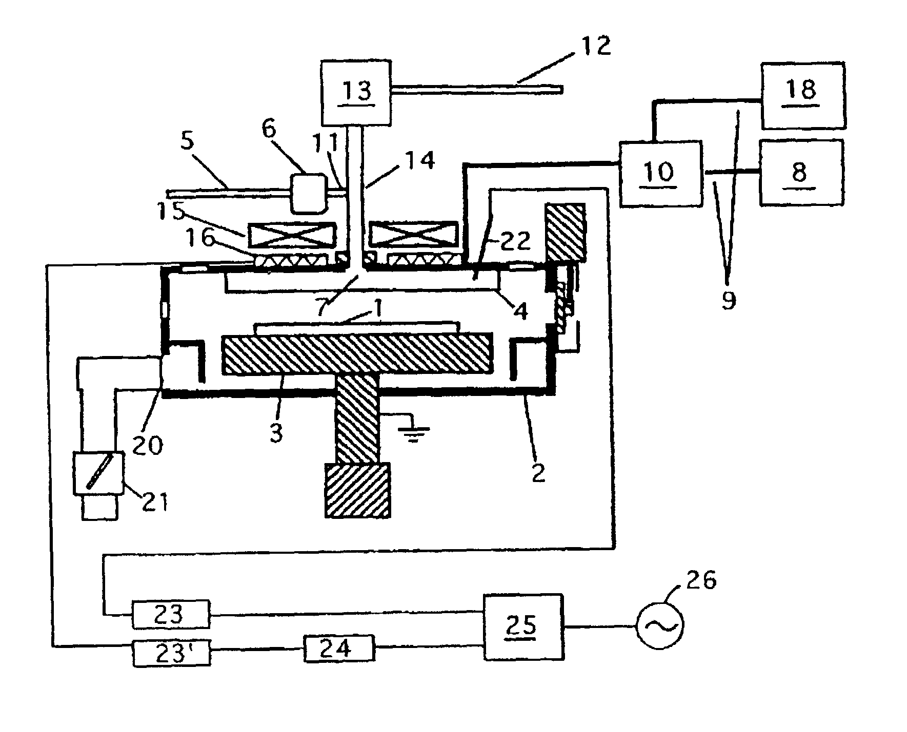
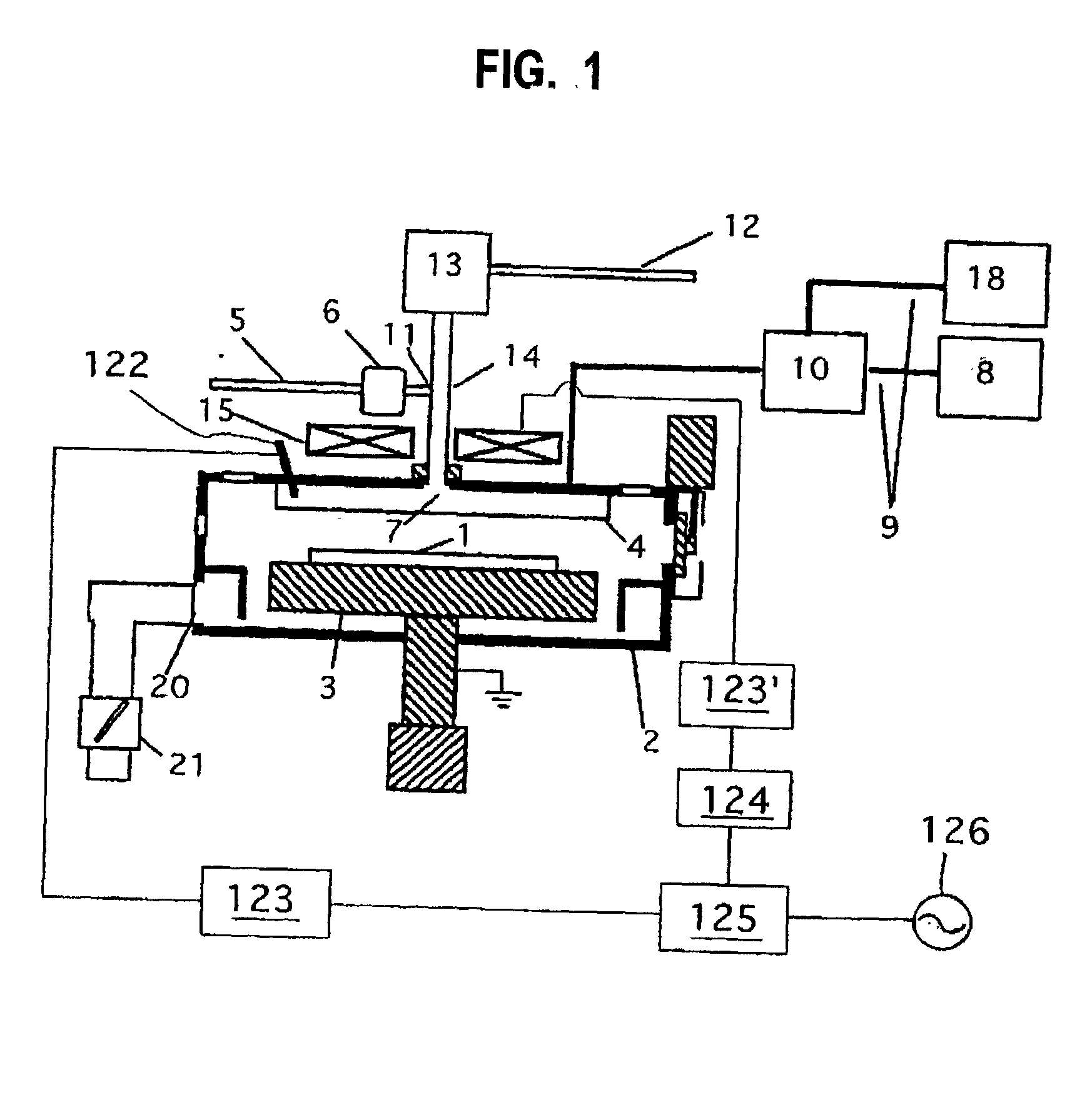
[0105] Using a conventional capacitive coupled plasma CVD apparatus shown in FIG. 1 and the capacitive coupled plasma CVD apparatus in Embodiment 2 according to the present invention shown in FIG. 6, comparative experiments of deposition rates, film thickness non-uniformity, cleaning rates, and cleaning cycle under conditions described below were conducted.

[0106] (1) Deposition Conditions:

[0107] Deposition conditions for the conventional capacitive coupled plasma CVD apparatus shown in FIG. 1 were: a TEOS flow of 250 sccm, an O.sub.2 flow of 2.3 slm, a distance between upper and lower electrodes of 10 mm, a showerhead diameter of .O slashed.350 mm, a lower electrode diameter of .O slashed.350 mm, a chamber pressure of 400Pa, a showerhead temperature of 150.degree. C., a susceptor temperature of 400.degree. C., a reaction chamber inner wall temperature of 140.degree. C., a radio-frequency power (13.56 MHz) at 600W and radio-frequency power (430 kHz) at 400W. Under th...


PUM

PropertyMeasurementUnit
temperatureaaaaaaaaaa
thicknessaaaaaaaaaa

Abstract

A plasma CVD apparatus conducting self-cleaning comprises a reaction chamber, a susceptor, a showerhead, a temperature controlling mechanism for directly controlling the temperature of the showerhead at a temperature of 200° C. to 400° C., a remote plasma discharge device provided outside the reaction chamber, and a radio-frequency power source electrically connected to either of the susceptor or the showerhead.

Description

[0001] 1. Field of the Invention[0002] The present invention relates to a plasma CVD (chemical vapor deposition) apparatus comprising a self-cleaning device. The present invention particularly relates to a plasma CVD apparatus which cleans the inside of a reaction chamber using active species generated remotely.[0003] 2. Description of the Related Art[0004] Generally, a plasma treatment apparatus is used for forming or removing films or for reforming the surface of an object-to-be-processed. In particular, thin film formation (by plasma CVD) on semiconductor wafers such as silicon or glass substrates or thin film etching is essential technique for manufacturing memories, semiconductor devices such as CPU's, or LCD's (Liquid Crystal Displays).[0005] Conventionally, the CVD apparatus has been used for forming silicon substrates or glass substrates provided with insulation films such as those of silicon oxide (SiO), silicon nitride (SiN), silicon carbide (SiC), and silicon oxide carbid...

Claims


Application Information

Patent Timeline
Patent Type & Authority Applications(United States)
IPC IPC(8): H01L21/205C23C16/44C23C16/455H01J37/32H01L21/285H01L21/302H01L21/3065H01L21/31
CPCC23C16/4405C23C16/45565C23C16/4557H01J37/32082H01J2237/3321H01J37/3244H01J37/32743H01J37/32788H01J37/32862H01J37/32091H01L21/205
Inventor FUKUDA, HIDEAKI
Owner ASM JAPAN
Why Eureka
Try Eureka