Catalytic cracking process of petroleum hydrocarbons

a petroleum hydrocarbon and cracking technology, applied in the direction of catalytic cracking, catalytic naphtha reforming, chemistry apparatus and processes, etc., can solve the problems of untiring research and study by refiners, product distribution and product properties cannot be improved by means of optimizing operation variables, and the cost of both equipment reconstruction and unit construction is increased significantly

Inactive Publication Date: 2003-06-26
CHINA PETROCHEMICAL CORP +1
View PDF9 Cites 41 Cited by
  • Summary
  • Abstract
  • Description
  • Claims
  • Application Information

AI Technical Summary

Problems solved by technology

Although catalytic cracking process has been developed for several decades and formed a relatively complete system of techniques, refiners are still studying and searching untiringly to seek for a process not only meeting the requirements of increasingly rigorous environmental laws and regulations but also according with the change of market demands so as to create satisfactory economic benefit for enterprises.
The first category of the processes need a little modi...

Method used


Image

  • Catalytic cracking process of petroleum hydrocarbons
  • Catalytic cracking process of petroleum hydrocarbons
  • Catalytic cracking process of petroleum hydrocarbons

Examples


example 2

[0076] The present example shows test results obtained by using the process provided in the present invention when a liquefied petroleum gas is produced as main object product.

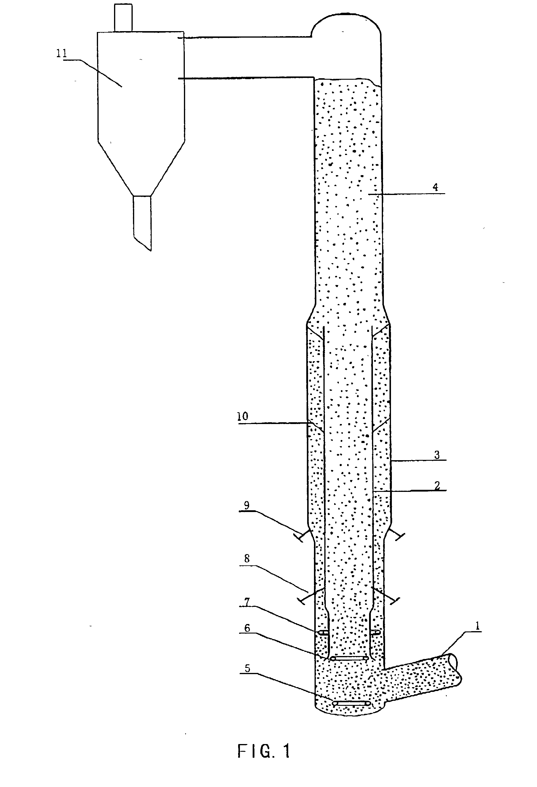
[0077] Main steps of the test are as follows The feedstock shown in Table 1 was heated via a preheating furnace, then fed to the inner tube of the tube-in-tube riser reactor to contact the regenerated catalyst flowing from the regenerator and lifted with a pre-lifting media. The light oil (gasoline diesel oil) with a distillation range less than 350.degree. C. produced in the present unit was fed into the annular space between the inner and outer tubes to contact the regenerated catalyst therein. Both the reaction stream from the inner tube and the reaction stream from the annular space moved up along vessel wall respectively, mixed with each other in the confluence tube to continue the reaction, and then entered a disengager. In the disengager, the hydrocarbon product stream was separated from the spent catal...

example 3

[0079] The present example shows test results obtained by using the process provided in the present invention when gasoline is produced as main object product.

[0080] The main steps of the test are as follows. The feedstock shown in Table 1 and the recycled oil produced in the present unit were mixed, then the mixed oil was heated via a preheating furnace and fed to the inner tube of the tube-in-tube riser reactor to contact the regenerated catalyst flowing from the regenerator and lifted with a pre-lifting media. Coker gasoline (with a density of 0.7316 g / cm.sup.3, RON=58.8, MON=65.4, an olefin content of 37.49% by weight) was fed to the annular space between the inner and outer tubes to contact the regenerated catalyst therein. Both the reaction stream in the inner tube and the reaction stream in the annular space moved up along vessel wall respectively, mixed with each other in the confluence tube to continue the reaction, and then entered a disengager. In the disengager, the hydr...

example 4

[0082] The present example shows test results obtained by using the process provided in the present invention when diesel oil is produced as main object product.

[0083] Main steps of test are as follows. As shown in FIG. 7, the feedstock shown in Table I was mixed with the recycled oil of the present unit, the mixed oil was heated via a preheating furnace and fed to the inner tube of the tube-in-tube riser reactor to contact the mixed catalyst from catalyst blending vessel 16 in which the regenerated catalyst and the spent catalyst were mixed. The coker diesel oil (with a density of 0.8520 g / cm.sup.5, a sulfur content of 8225 ppm, and a nitrogen content of 5018 ppm, and a cetane number of 47) was fed to the annular space between the inner and outer tubes to contact the mixed catalyst therein. Both the reaction stream in the inner tube and the reaction stream in the annular space moved up along vessel wall respectively, then mixed with each other in the confluence tube to continue the...


PUM


Abstract

The present invention discloses a catalytic cracking process of petroleum hydrocarbons and a tube-in-tube riser reactor used therein. In the present invention, a catalyst is fed via an inlet conduit to an inner tube and an annular space between the inner and outer tubes of the tube-in-tube riser reactor to contact a hydrocarbon feedstock, and the hydrocarbon feedstock is cracked under FCC conditions, then a reaction stream thus produced flows into a separation apparatus via a confluence tube to separate a hydrocarbon product stream from a spent catalyst, the spent catalyst is stripped and regenerated, then a regenerated catalyst is recycled for reuse. The process of the present invention can improve both product distribution and product properties.

Description

TECHNIQUE FIELD[0001] The present invention relates to a catalytic cracking process of petroleum hydrocarbons ire the absence of hydrogenTECHNIQUE BACKGROUND[0002] Although catalytic cracking process has been developed for several decades and formed a relatively complete system of techniques, refiners are still studying and searching untiringly to seek for a process not only meeting the requirements of increasingly rigorous environmental laws and regulations but also according with the change of market demands so as to create satisfactory economic benefit for enterprises.[0003] U.S. Pat. No. 5,043,522 and U.S. Pat. No. 5,846,403 relate to the improvements of conventional catalytic cracking process, in which part of catalytic gasoline is fed to a riser reactor at upstream of the feedstock nozzles to contact a regenerated catalyst having high activity at a high temperature, so that the yields of light olefins such as propylene, butylene and the like are increased, meanwhile the octane...

Claims


Application Information

Patent Timeline
IPC IPC(8): B01J8/00B01J8/18B01J8/24B01J8/26B01J8/30B01J8/32B01J8/34B01J19/26C10G11/18
CPCB01J8/0025C10G11/18B01J8/004B01J8/0055B01J8/1809B01J8/1818B01J8/1827B01J8/1845B01J8/1872B01J8/26B01J8/28B01J8/30B01J8/32B01J8/34B01J19/26B01J2208/00548B01J2208/00557B01J8/003
Inventor ZHANG, RUICHIZHONG, XIAOXIANGZHANG, JIUSHUNXU, KEJIAZHANG, ZHIGANGHOU, SHUANDICHANG, XUELIANGWU, ZHIGUO
Owner CHINA PETROCHEMICAL CORP
Why Eureka
Try Eureka