

Rolling bearing
- Summary
- Abstract
- Description
- Claims
- Application Information
AI Technical Summary
Benefits of technology
Problems solved by technology
Method used
Image

Examples
Embodiment Construction
[0034] Preferred embodiments of the present invention are to be explained below.
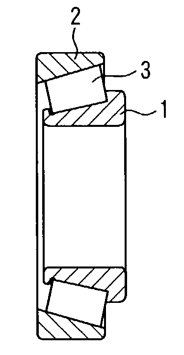
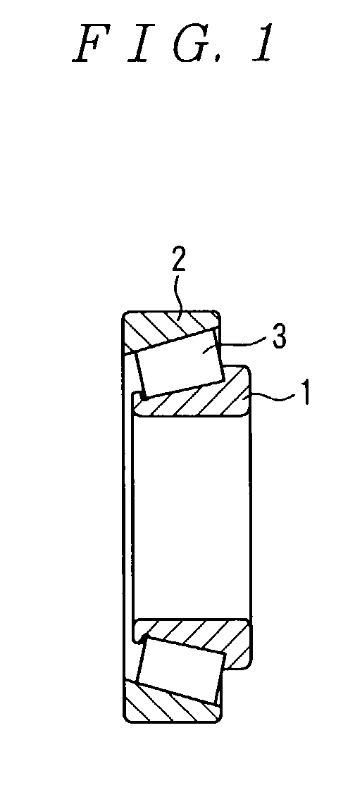
[0035] FIG. 1 is a cross sectional view of a rolling bearing of this embodiment. The rolling bearing is a tapered roller bearing having an outer diameter .phi.1 of 130 mm, an inner diameter .phi. of 85 mm and a width of 30 mm. In the drawing, are shown an inner ring 1, an outer ring 2 and a rolling element (tapered roller) 3. As has been described previously, the inner ring 1 of the tapered roller bearing is formed with a flange for supporting the rolling element 3 as described above.
[0036] At first, as shown in the following Table 1, test specimens A-H of examples having chemical ingredients within the recommended range and test specimens I-M of comparative examples having chemical ingredients out of the recommended range with respect to the elements indicated by underlines were provided.
1 TABLE 1 Test Specimen C Si Mn Cr Mo Remarks Example A 0.2 0.8 0.5 1.5 -- B 0.4 1.0 0.4 1.5 -- C 0.4 1.0 1.0 1.5 -- ...
PUM
| Property | Measurement | Unit |
|---|---|---|
| Fraction | aaaaa | aaaaa |
| Temperature | aaaaa | aaaaa |
| Temperature | aaaaa | aaaaa |
Abstract
Description
Claims
Application Information