
Color filter

a color filter and filter body technology, applied in the field of color filters, can solve the problems of poor light resistance and color hue fading during use over long periods, and the inability to achieve the desired chromaticity or color hue in the pixel portions, and achieve the effect of stronger yellowish tinge and more durabl

Inactive Publication Date: 2003-08-14
DAINIPPON INK & CHEM INC
View PDF0 Cites 42 Cited by
  • Summary
  • Abstract
  • Description
  • Claims
  • Application Information

AI Technical Summary

Benefits of technology

[0019] An object to be achieved by the present invention is to provide a color filter which is more durable than a dye-type color filter and also has green pixel portions which can produce a bright green color having a stronger yellowish tinge when used in a liquid crystal display device using a three-band lamp having a main emission line of green light of about 545 nm as a light source, and thus enabling the liquid crystal display device to display bright images even when using a backlighting light source having a low intensity.

Problems solved by technology

However, these dyes have drawbacks in that they are inferior in the durability of various characteristics such as light resistance.
However, as a backlighting light source of a liquid crystal display device, a three-band lamp having a main emission line of green light of about 545 nm is used, and the following problems arise when using the above-described conventional color filter in a liquid crystal display device using this light source.
Sho 63-286801 has fundamental drawbacks such as poor light resistance and fading of color hue during use over long periods.
However, the amount of the yellow pigment to be added to the green pigment for the purpose of achieving this object is high, thus portions with neither desired chromaticity nor desired color hue in the pixel portions are sometimes formed for the following reason.
Consequently, a color filter having such pixel portions has drawbacks in that the resulting liquid crystal display has insufficient brightness and a backlighting light source with a high intensity must be used to display satisfactory bright images, and that portions with neither desired chromaticity nor desired color hue is formed in the pixel portions.

Method used


Image

  • Color filter
  • Color filter
  • Color filter

Examples


preparation example 1

[0107] Using phthalic anhydride, urea, and aluminum chloride as raw materials, chloroaluminum phthalocyanine was prepared. A 1-chloronaphthalene solution of the chloroaluminum phthalocyanine exhibited an absorption of light at a wavelength within a range from 650 to 750 nm.

[0108] As a halogenating agent, a mixture was prepared by mixing 3.2 parts of thionyl chloride, 3.8 parts of anhydrous aluminum chloride, and 0.5 parts of sodium chloride at 40.degree. C. and adding dropwise 2.7 parts of bromine. To the mixture, 1 part of chloroaluminum phthalocyanine was added, and the reaction was conducted at 90.degree. C. for 15 hours. After the completion of the reaction, the reaction mixture was poured into water to deposit a crude halogenated chloroaluminum phthalocyanine pigment. The aqueous slurry was collected by filtration, washed, in order, with hot water at 60.degree. C., 1% sodium hydrogensulfate water, and hot water at 60.degree. C., and then dried at 90.degree. C. to obtain 2.7 par...

preparation example 2

[0111] Using phthalic anhydride, urea, and vanadium pentoxide as raw materials, oxyvanadium phthalocyanine was prepared. A 1-chloronaphthalene solution of the oxyvanadium phthalocyanine exhibited an absorption of light at a wavelength within a range from 650 to 750 nm.

[0112] As a halogenating agent, a mixture was prepared by mixing 3.1 parts of thionyl chloride, 3.7 parts of anhydrous aluminum chloride, and 0.5 parts of sodium chloride at 40.degree. C. and adding dropwise 2.6 parts of bromine. To the mixture, 1 part of oxyvanadium phthalocyanine was added, and the reaction was conducted at 90.degree. C. for 15 hours. After the completion of the reaction, the reaction mixture was poured into water to deposit a crude halogenated oxyvanadium phthalocyanine pigment. The aqueous slurry was collected by filtration, washed, in order, with hot water at 60.degree. C., 1% sodium hydrogensulfate water, acetone containing 7% toluene, and hot water at 60.degree. C., and then dried at 90.degree. ...

preparation example 3

[0115] Using phthalodinitrile and zinc chloride as raw materials, zinc phthalocyanine was prepared. A 1-chloronaphthalene solution of the zinc phthalocyanine exhibited an absorption of light at a wavelength within a range from 650 to 750 nm.

[0116] As a halogenating agent, a mixture was prepared by mixing 3.1 parts of thionyl chloride, 3.7 parts of anhydrous aluminum chloride, and 0.5 parts of sodium chloride at 40.degree. C. and adding dropwise 2.6 parts of bromine. To the mixture, 1 part of zinc phthalocyanine was added, and the reaction was conducted at 90.degree. C. for 15 hours. After the completion of the reaction, the reaction mixture was poured into water to deposit a crude halogenated zinc phthalocyanine pigment. The aqueous slurry was collected by filtration, washed, in order, with hot water at 60.degree. C., 1% sodium hydrogensulfate water, acetone containing 7% toluene, and hot water at 60.degree. C., and then dried at 90.degree. C. to obtain 2.6 parts of a purified crude...


PUM


Abstract

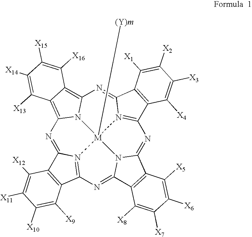
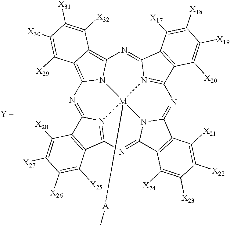
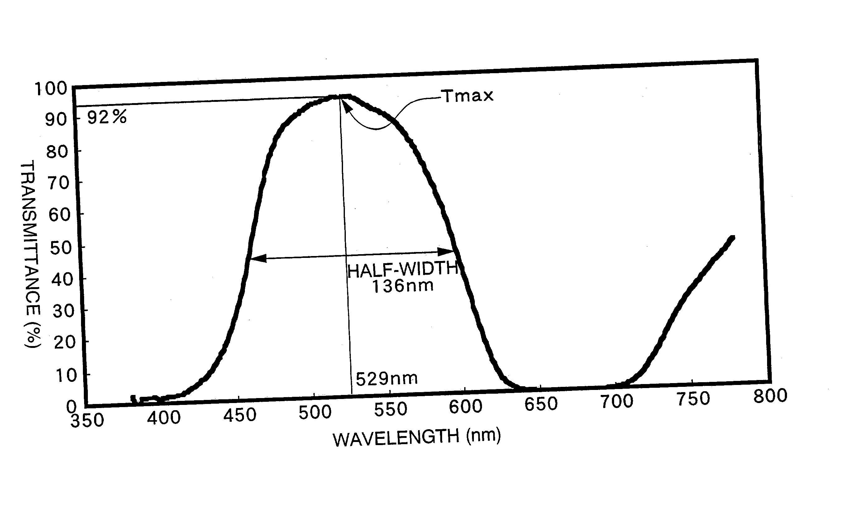
The present invention provides a color filter which is more durable than a dye-type color filter and also has green pixel portions which exhibit a bright green color having a strong yellowish tinge when used in a liquid crystal display device using a three-band lamp having a main emission line of green light of about 545 nm as a light source, thus enabling the liquid crystal display device to display bright images even when using a backlighting light source having a low intensity. This color filter comprises green pixel portions which (1) contain a halogenated metal phthalocyanine dye wherein 8 to 16 halogen atoms are bonded to benzene rings in one phthalocyanine molecule, and (2) exhibit maximum transmittance at a wavelength within a range from 520 nm to 590 nm with respect to the transmission spectra of the entire range of visible light.

Description

[0001] The present invention relates to a color filter comprising green pixel portions containing a halogenated metal phthalocyanine pigment.[0002] In a liquid crystal display device, a color filter comprises a transparent substrate on which red pixel portions, green pixel portions, and blue pixel portions are formed, and halogenated copper phthalocyanine dyes or halogenated copper phthalocyanine pigments are generally used for the green pixel portions.[0003] As a green colorant for the green pixel portions of the color filter, there is used a dye or pigment having a structure of a halogenated metal phthalocyanine wherein 8 or more halogen atoms are bonded to benzene rings in one phthalocyanine molecule. However, for dyes or pigments used in the field of color filters, which are different from those for general purposes such as lithographic inks, paints, and coloring of molded articles, there is required not only coloring characteristics, but also the following higher characteristic...

Claims


Application Information

Patent Timeline
IPC IPC(8): C09B47/10G02B5/22
CPCG02B5/223C09B47/10G02B5/20
Inventor FUNAKURA, SEIJIYAO, IEMASAKUDOU, ARATAKIUCHI, EIICHIKATSUBE, HIROSHI
Owner DAINIPPON INK & CHEM INC
Learn More