Planar light illumination and linear imaging (PLILIM) device with image-based velocity detection and aspect ratio compensation

a technology of linear imaging and planar light, which is applied in the direction of instruments, electrical appliances, computing, etc., can solve the problems of large percentage of illumination waste, increased cost, size and weight of such scanning devices, and simple waste of output illumination power in the form of heat, so as to reduce speckle noise, reduce cost, and reduce cost

Inactive Publication Date: 2003-08-21
METROLOGIC INSTR
View PDF55 Cites 48 Cited by
  • Summary
  • Abstract
  • Description
  • Claims
  • Application Information

AI Technical Summary

Benefits of technology

0059] Another object of the present invention is to provide improved methods of and devices for image acquisition utilizing a plurality of lower cost linear imaging arrays to produce a plurality of composite two-dimensional (2D) digital images of at least one target object, and image-based mechanisms / techniques that analyze the plurality of composite 2-D digital images to derive velocity data that estimates relative velocity of the target object and output such velocity data to a controller that updates the operating parameters of an illumination source (e.g., illumination power parameters, duty cycle parameters, etc) based upon the velocity data to compensate for changes in the relative object velocity as estimated by the velocity data.
0060] Another object of the present invention is to provide improved methods of and devices for image acquisition utilizing a plurality of lower cost linear imaging arrays to produce a plurality of composite two-dimensional (2D) digital images of at least one target object, and image-based mechanisms / techniques that analyze the plurality of composite 2-D digital images to derive velocity data that estimates relative velocity of the target object and output such velocity data to a controller that updates the operating parameters (e.g., orientation parameters, focus parameters, zoom parameters, exposure parameters, etc.) of a camera subsystem based upon the velocity data to compensate for changes in the relative object velocity as estimated by the velocity data.
0061] A further object of the present invention is to provide improved methods of and devices for image acquisition that utilize a plurality of linear imaging arrays, at least one illumination module (including at least one coherent light source, e.g., VLD) that produces planar light illumination that substantially overlaps the field of views corresponding to the plurality of linear imaging arrays during image capture operations that produce digital images, and one or more of despeckling mechanisms to reduce speckle noise in such digital images.
0062] A further object of the present invention is to provide improved methods of and devices for image acquisition that utilize at least one imaging array, at least one illumination module (including at least one coherent light source, e.g. VLD) that produces planar light illumination that substantially overlaps the field of view corresponding to the imaging array during image capture operations that produce digital images, and illumination control circuitry that modulates the power level of illumination produced by the coherent light source during each photo-integration time period of the imaging array to thereby reduce speckle noise in images captured by the imaging array.
0063] Another object of the present invention is to provide such improved methods of and devices for image acquisition, whereby the illumination control circuitry modulates the power level of illumination by controlling the number and / or duration of time periods corresponding to different power levels of illumination produced by the coherent light source during each photo-integration time period of the imaging array.
0064] Another object of the present invention is to provide such improved methods of and devices for image acquisition, whereby the illumination control circuitry controls number and / or duration of such time periods such that substantially constant energy is produced by the coherent light source over the time periods (thereby enabling the different speckle patterns produced over the time periods to optimally cancel each other out).

Problems solved by technology

Consequently, only a small percentage of the illumination is actually collected by the imaging optics of the system, and a large percentage of the illumination is wasted.
However, even with such improvements in LED illumination techniques, the working distance of such hand-held scanners can only be extended by using more LEDs within the scanning head of such scanners to produce greater illumination output therefrom, thereby increasing the cost, size and weight of such scanning devices.
Most prior art CCD-based image scanners employed in conveyor-type package identification systems require high-pressure sodium, metal halide or halogen lamps and large, heavy and expensive parabolic or elliptical reflectors to produce sufficient light intensities to illuminate the large depth of field scanning fields supported by such industrial scanning systems.
The balance of the output illumination power is simply wasted in the form of heat.
While the prior art laser-illuminated CCD-based image capture systems discussed above avoid the use of LED illumination, they suffer from several significant shortcomings and drawbacks.
For example, when detecting images of target objects illuminated by a coherent illumination source (e.g. a VLD), "speckle" (i.e. substrate or paper) noise is typically modulated onto the laser illumination beam during reflection / scattering, and ultimately speckle-noise patterns are produced at the CCD image detection array, severely reducing the signal-to-noise (SNR) ratio of the CCD camera system.
Importantly, the prior art systems described above fail to provide any way of, or means for reducing speckle-noise patterns produced at its CCD image detector thereof, by its coherent laser illumination source.
However, the prior art generally fails to disclose, teach or suggest how such prior art speckle-reduction techniques might be successfully practiced in a laser illuminated hand-held bar code symbol reader.
However, the use of the lower-cost linear imaging array in capturing images introduces problems.
One problem is aspect ratio variations / distortions in the images captured by the linear imaging array.
If such distortion is significant, it can render the bar code symbol reader ineffective in many applications, such as reading dense 2-D bar code symbols.
Another problem is jitter (motion of the object relative to device in a direction transverse to the intended swipe direction).
If such horizontal jitter is significant, the resulting image distortions can degrade the quality of the images captured by the device and lead to errors / inaccuracies in subsequent image analysis operations (such as bar code symbol detections operations and / or OCR operations) performed on these images.
Consequently, only a small percentage of the illumination is actually collected by the imaging optics of the system, and a large percentage of the illumination is wasted.
Moreover, the prior art generally fails to disclose, teach or suggest image-based techniques / devices that measure velocity variations of the imaging device with respect to the object to be scanned and compensate for aspect ratio distortions that result from such velocity variations, which are suitable for use in a hand-held bar code symbol reader.
Moreover, the prior art generally fails to disclose, teach or suggest image-based techniques / devices that perform velocity estimation / aspect ratio compensation in addition to image-based jitter estimation and compensation to compensate for both aspect ratio distortion and jitter distortion, which are suitable for use in a hand-held bar code symbol reader.

Method used


Image

  • Planar light illumination and linear imaging (PLILIM) device with image-based velocity detection and aspect ratio compensation
  • Planar light illumination and linear imaging (PLILIM) device with image-based velocity detection and aspect ratio compensation
  • Planar light illumination and linear imaging (PLILIM) device with image-based velocity detection and aspect ratio compensation

Examples


Embodiment Construction

[0149] Referring to the figures in the accompanying Drawings, the various illustrative embodiments of an PLILM-based imaging device in accordance with the present invention will be described in great detail.

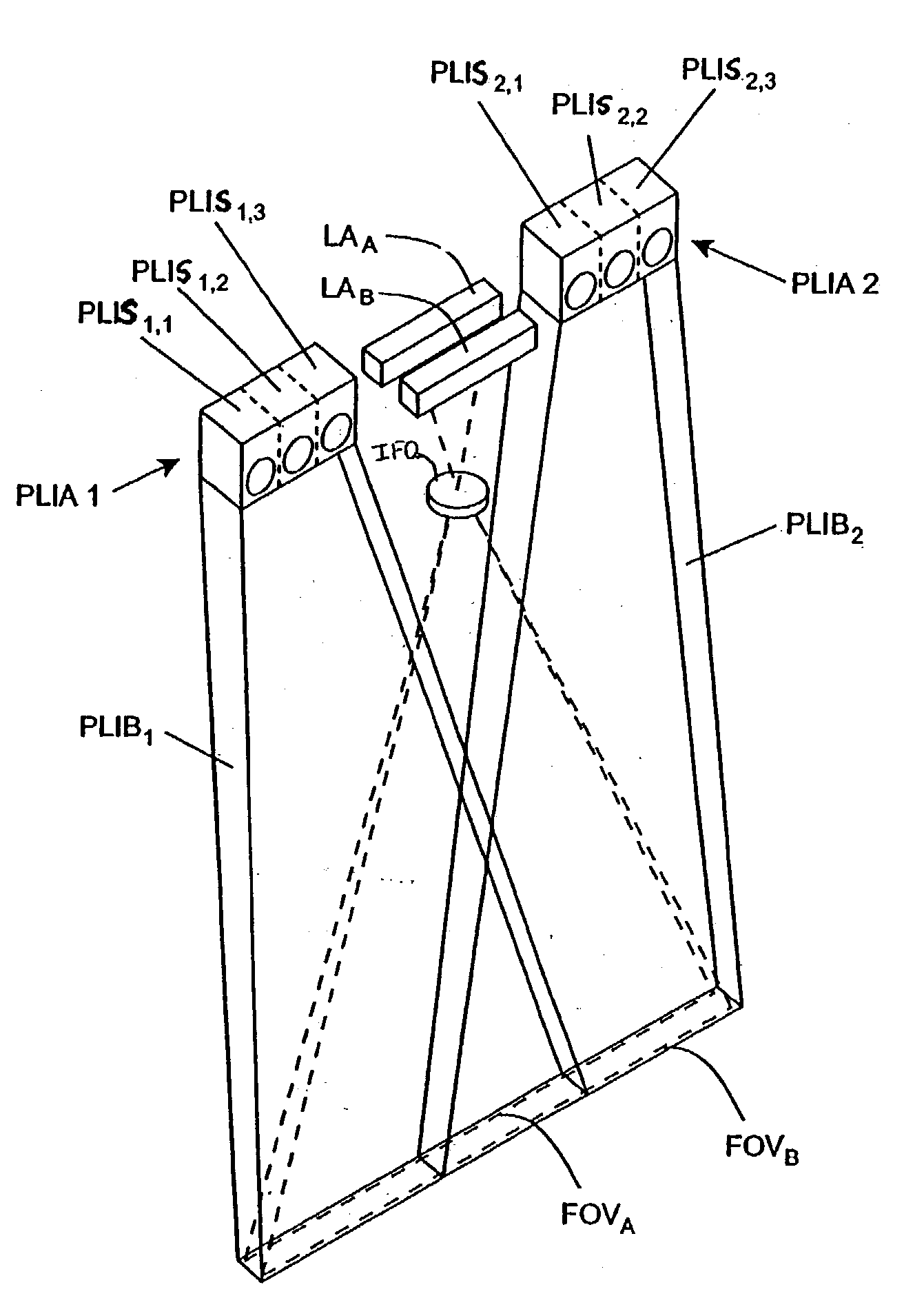
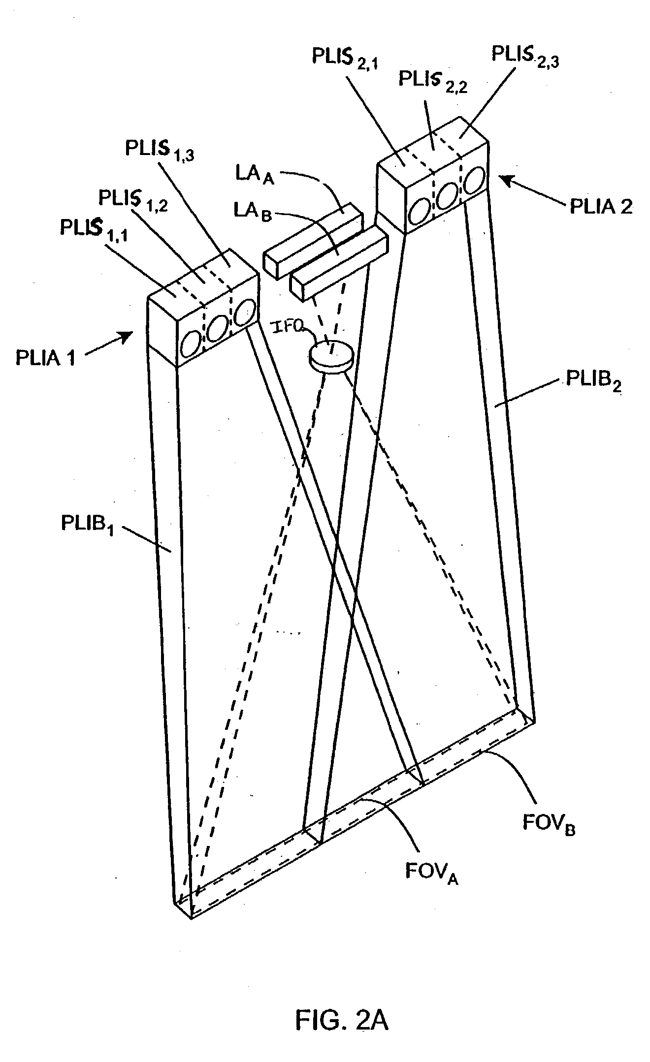
[0150] In accordance with the principles of the present invention, a target object (e.g. a bar coded package, textual materials, graphical indicia, etc.) is illuminated by planar light illumination--which is light illumination having substantially-planar spatial distribution along a characteristic propagation direction. In other words, the planar light illumination has a width of illumination (which extends along a transverse direction to the characteristic direction of propagation as best shown in FIG. 2F2) that is much greater than its height of illumination (which extends along a direction orthogonal to the characteristic propagation direction as best shown in FIG. 2F3). The planar light illumination overlaps the field of views (FOVs) of a plurality of linear (1-D) imaging arr...


PUM


Abstract

An imaging device comprising a plurality of linear imaging arrays and image formation optics that provide field of views corresponding to the plurality of linear image arrays. At least one illumination module produces planar light illumination that substantially overlaps the field of views corresponding to the plurality of linear imaging arrays. Image processing circuitry performs image-based velocity estimation operations, which analyzes pixel data values of a plurality of composite 2-D images each derived from sequential image capture operations of a corresponding one linear imaging array to derive velocity data that represents an estimated velocity of the imaging device with respect to at least one target object disposed in the fields of view. Preferably, the image processing circuitry also produces a first image of portions of the target object(s), the first image having substantially constant aspect ratio, utilizing image transformation operations (or camera control operations) that are based upon the velocity data, to thereby compensate for aspect ratio distortions that would otherwise result from variations in velocity of the imaging device with respect to the target object(s). In addition, the image processing circuitry preferably carries out image-based horizontal jitter estimation and compensation operations, which estimate the horizontal jitter of the imaging device relative to the target object(s) over the image capture operations from which the first image is derived and transform the first image utilizing shift operations that are based upon such estimated horizontal jitter to produce a second image of portions of the target object(s) which compensates for horizontal jitter distortion that would otherwise result therefrom. The first image or second image (or image derived from sharpening the first or second images) is preferably subject to image-based bar code detection operations and/or OCR operations, or output for display to a display device.

Description

CROSS-REFERENCE TO RELATED U.S. APPLICATION[0001] This application is related to copending Application No. PCT / US01 / 44011 filed Nov. 21, 2001, published by WIPO as WO 02 / 43195 A2, said application being commonly owned by Assignee, Metrologic Instruments, Inc., of Blackwood, N.J., and incorporated herein by reference as if fully set forth herein in its entirety.[0002] 1. Field of Invention[0003] The present invention relates generally to improved methods of and apparatus and instruments for acquiring and analyzing information about the physical attributes of objects (such as reading bar code labels affixed to such objects), and digital image analysis.[0004] 2. Brief Description Of The State Of Knowledge In The Art[0005] The use of image-based bar code symbol readers and scanners is well known in the field of auto-identification. Examples of image-based bar code symbol reading / scanning systems include, for example, hand-hand scanners, point-of-sale (POS) scanners, and industrial-type ...

Claims


Application Information

Patent Timeline
Patent Type & Authority Applications(United States)
IPC IPC(8): H04N1/193G06V10/12H04N1/46
CPCG06K9/2009H04N1/193H04N2201/04703H04N2201/04712H04N2201/04734H04N2201/04743G06V10/12
Inventor SCHNEE, MICHAEL D.ZHU, XIAOXUNKNOWLES, CARL HARRY
Owner METROLOGIC INSTR
Why Eureka
Try Eureka