

Gas turbine seal
- Summary
- Abstract
- Description
- Claims
- Application Information
AI Technical Summary
Benefits of technology
Problems solved by technology
Method used
Image

Examples
Embodiment Construction
[0026] The invention is explained in more detail below with reference to exemplary embodiments and FIGS. 1 to 5.
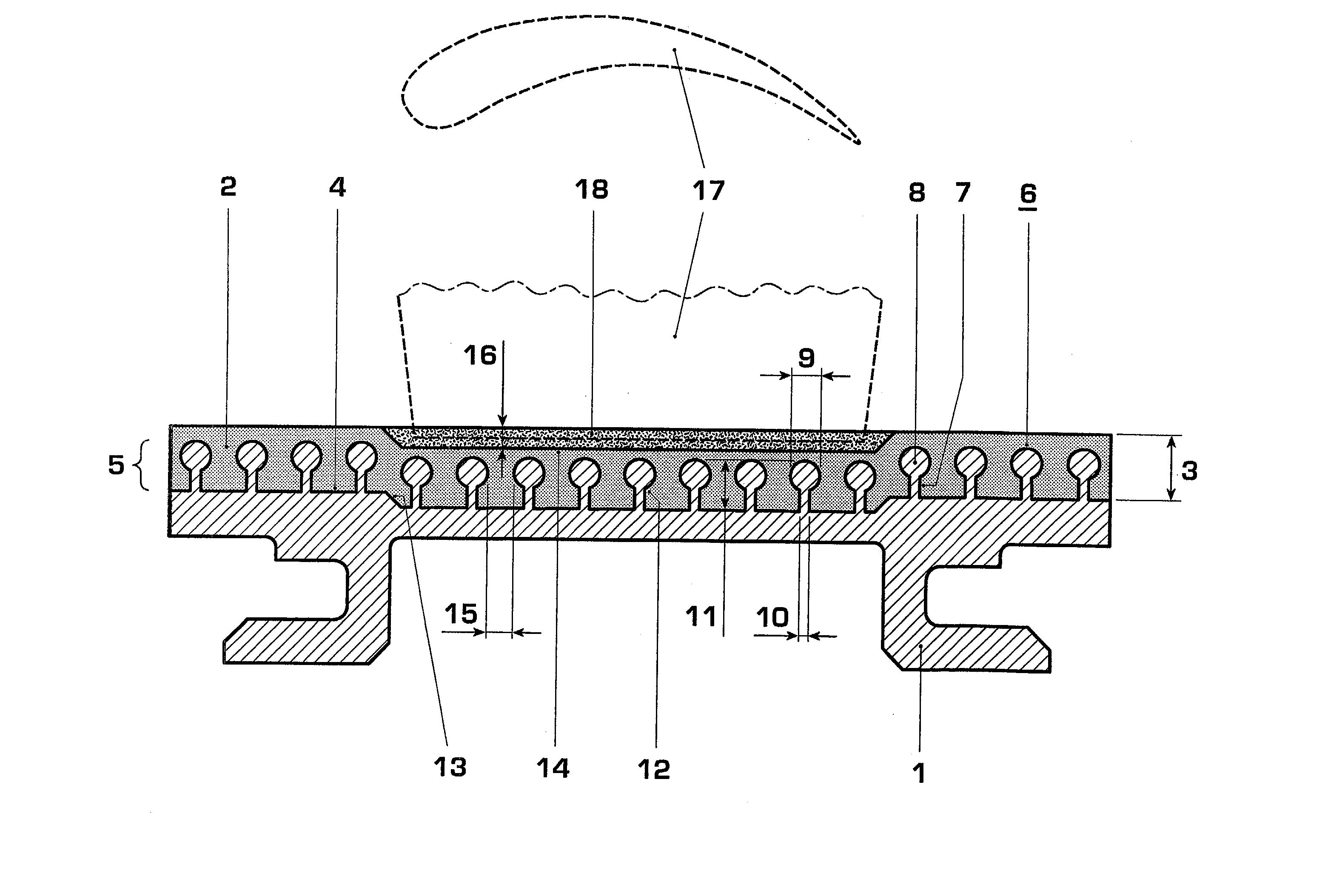
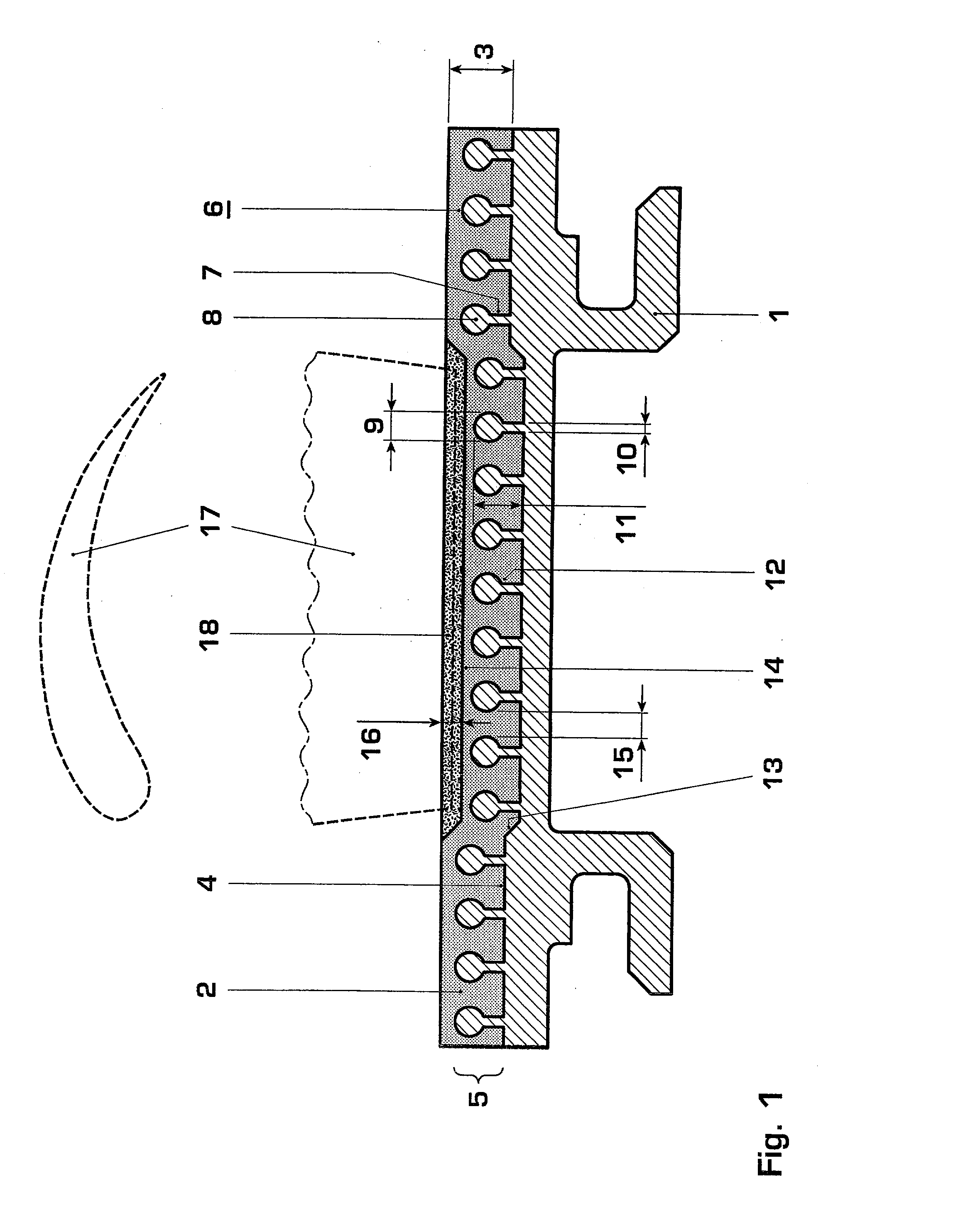
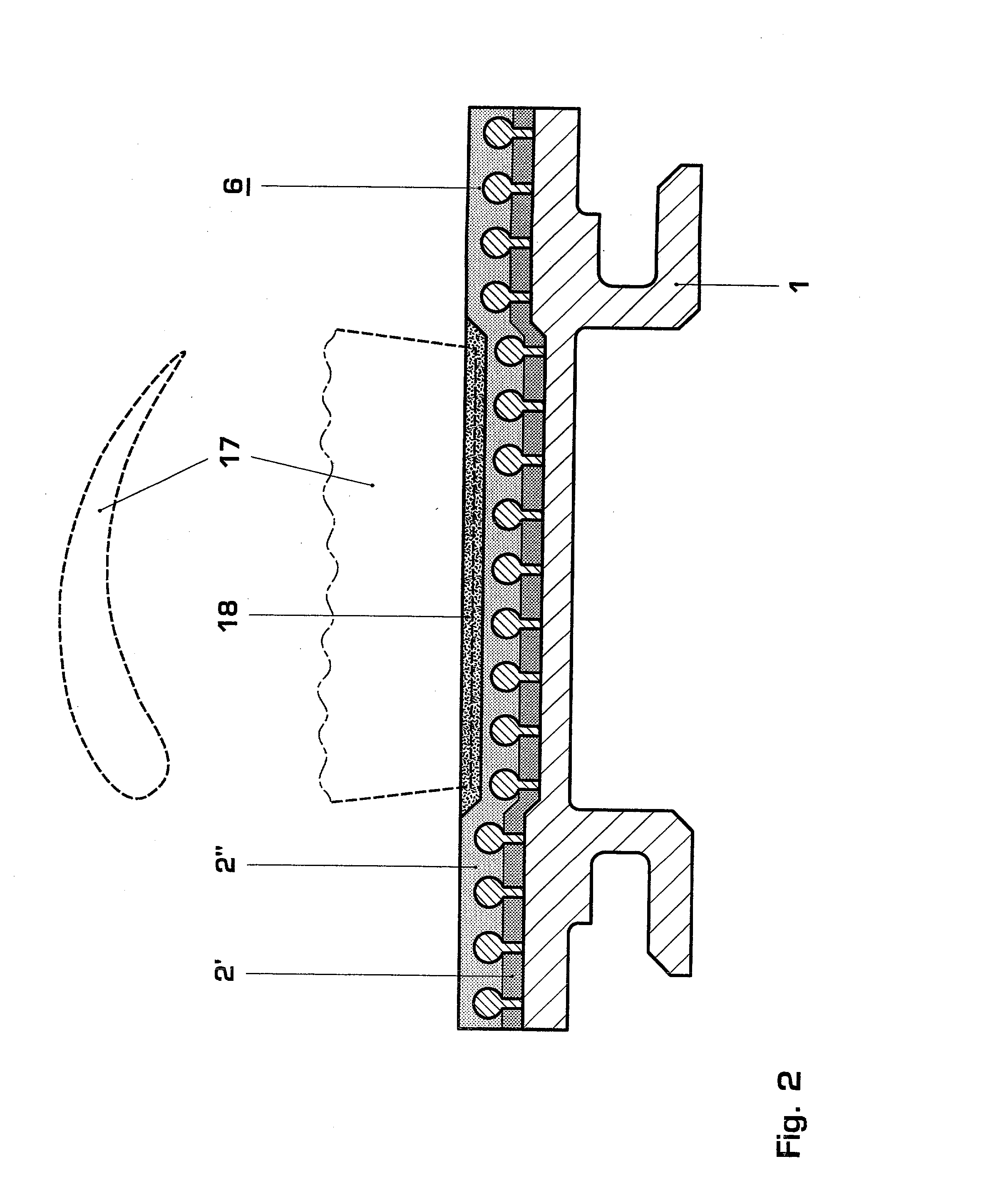
[0027] FIGS. 1 to 5 illustrate sections through four different variants of the gas turbine seal according to the invention. The figures in each case show a blade or vane tip seal.
[0028] FIG. 1 shows a blade or vane tip seal of a gas turbine, which comprises a metallic component 1, on which a durable or erosion-resistant ceramic layer 2, for example a thermal barrier coating comprising yttrium-stabilized zirconia of the following chemical composition: 2.5% of HfO.sub.2, 7-9% of Y.sub.2O.sub.3, <3% of others, remainder ZrO, is sprayed by means of plasma spraying. Application by means of flame spraying is also possible. The layer 2 has a constant layer thickness 3, i.e. it follows the surface contour of the component 1, which as shown in FIG. 1 does not have a planar surface 4, but rather has a step 13. Therefore, at this location the layer 2 has a cavity 14.
[0029] To improve...
PUM
 Abstract
Description
Claims
Application Information