
Method for controlling reaction and controlling apparatus

a technology of reaction apparatus and control apparatus, which is applied in the preparation of carboxylic compounds, carbon monoxide reaction carboxylic compounds, organic chemistry, etc., can solve the problems of unstable carbon monoxide consumption rate or usage rate difficult stabilization of the reaction system, and inability to effectively use carbon monoxide in the carbonylation reaction

Inactive Publication Date: 2003-09-25
DAICEL CHEM IND LTD
View PDF4 Cites 7 Cited by
  • Summary
  • Abstract
  • Description
  • Claims
  • Application Information

AI Technical Summary

Benefits of technology

[0008] The inventors of the present invention made intensive studies to achieve the above objects, and finally found that (1) even when a separated component (such as a high boiling point component or fraction, etc.), which has been separated by distillation from a carbonylation reaction mixture, is circulated (or returned) to the reaction system (i.e., the pressurized reaction system) steadily at a predetermined rate, the circulation rate (return flow rate) of the separated component will fluctuate, the temperature of the reaction system will fluctuate accordingly, the pressure of the reaction system will fluctuate in accompaniment with this temperature change even when carbon monoxide is supplied to the reaction system steadily at a predetermined rate, and the above-mentioned temperature and pressure fluctuations will be large especially in the case where the reaction temperature of an exothermic reaction system is controlled by the circulation rate (return flow rate) of the separated component and without using a cooling unit, and that (2) when the temperature of the circulated separated component is controlled according to (or depending on) the heat quantity of the separated component that is returned to the reaction system, the temperature and pressure fluctuations of the reaction system can be suppressed (or restrained) effectively, the discharge amount of carbon monoxide can be reduced to enable effective use of carbon monoxide for reaction, and the reaction system can be stabilized. The present invention was accomplished based on the above finding.
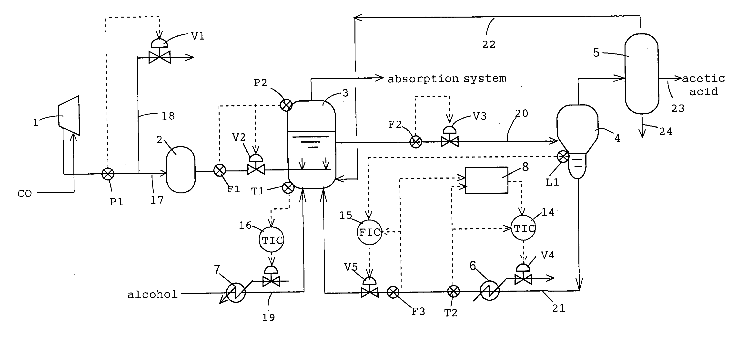
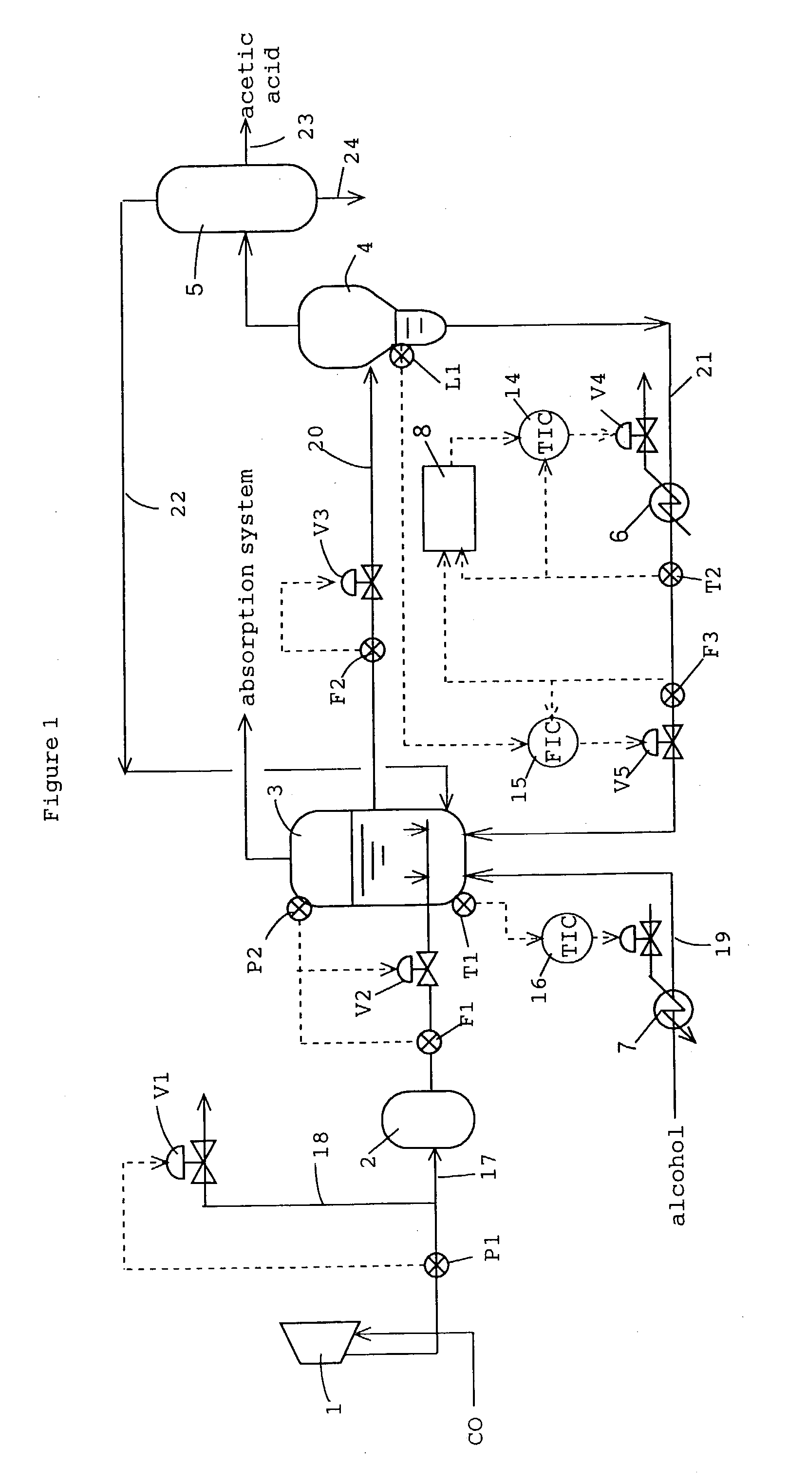
[0024] A level sensor L1, for detecting the height of the liquid level of the liquid phase, is mounted onto the lower part of the flash distillation column 4. Furthermore a temperature sensor T2, for detecting the temperature of the first high boiling point component (liquid component) that is returned to the reaction system, and a flow rate sensor F3, for detecting the flow rate of the first high boiling point component, are mounted onto the circulation line 21. The detection data from this temperature sensor T2 are sent or transmitted to the control unit 14, and this control unit controls the temperature of the high boiling point component by means of a heat medium flow rate regulating valve V4 and a temperature control unit (heat exchanger) 6, provided at the first circulation line 21. Furthermore, the detection data with respect to the height of the liquid level provided by the above-mentioned level sensor L1 and the detection data from the above-mentioned flow rate sensor F3 are transmitted or provided to the control unit 15, and based on these detection data, this control unit controls the circulation rate (return flow rate) of the high boiling point component by means of the flow rate regulating valve V5 provided in the first circulation line 21 to thereby maintain the liquid level at the flash distillation column 4 at a predetermined height position.
[0029] With a process equipped with such a control device, even when the circulation rate (return rate) of the high boiling point component in the first circulation line 21 fluctuates, since the heat quantity of the circulated high boiling point component is controlled in accordance with (or in response to) the circulation rate (return rate) of the high boiling point component that occupies a large portion of the flows returned to the reaction system, temperature fluctuations and pressure fluctuations within the reactor 3 can be suppressed significantly and the acetic acid production process can be stabilized. For example, when acetic acid is industrially produced under the conditions of the above-described acetic acid production plant, the temperature of the reaction system can be controlled in an extremely stable manner with respect to the reference temperature, that is for example, within a range of reference temperature .+-.0.5.degree. C. (preferably within a range of reference temperature .+-.0.3.degree. C. and especially within a range of reference temperature .+-.0.2.degree. C.). Furthermore, since temperature and pressure fluctuations (variations) can be suppressed or inhibited and the reaction system can be stabilized, not only the carbon monoxide feed rate and methanol feed rate but the acetic acid production rate can also be increased. Furthermore, the discharge rate of carbon monoxide from the exhaust line 18 can be reduced and the carbon monoxide can thus be utilized effectively in the carbonylation reaction.
[0050] The first high boiling point component and / or the second high boiling point component may contain high boiling point byproducts in some cases. Also, the first low boiling point component and / or the second low boiling point component may contain low boiling point byproducts in some cases. Thus the high boiling point byproducts or low boiling point byproducts may be separated if necessary from such high boiling point or low boiling point components, and in cases where components that are effective to the reaction are contained, the component containing effective components may be circulated to the reaction system. Further, as has been disclosed in Japanese Patent Application Laid-open No. 321847 / 1994 (JP-6-321847A), a high boiling point component may be made to contain water (at an amount for example of about 0.5 to 30 weight % and preferably about 1 to 15 weight %) for preventing precipitation or sedimentation (or deposition) and stabilizing the catalytic system.
[0053] Though in the above-described example, the temperature of the reaction system is controlled by controlling the heat quantity of the first high boiling point component, the heat quantity of the second low boiling point component that is circulated to the reaction system may also be controlled to control or regulate the temperature of the reaction system even more precisely. For example, the flow rate and temperature of the second low boiling point component may be detected by means of a flow rate sensor and a temperature sensor in the second circulation line and the temperature of the circulated second low boiling point component (the heat quantity of the second low boiling point component) may be controlled based on the detection data from the flow rate sensor and temperature sensor by the same control unit and temperature control unit as described above to control the temperature of the above-mentioned reaction system at a predetermined temperature and to restrain pressure fluctuations of the gas phase of the above-mentioned reaction system.

Problems solved by technology

However with such carbonylation reactions, the temperature and pressure of the reaction system fluctuate or vary with the circulation of the high boiling point component to the reaction system, causing the carbon monoxide consumption rate or usage rate of the reaction system to fluctuate and thus making the stabilization of the reaction system difficult.
Carbon monoxide therefore could not be used effectively in the carbonylation reaction.
With this method, since the carbon monoxide flow rate is controlled using a maximum flow rate, determined by adding a fixed value to the average carbon monoxide flow, as a reference, it is difficult to suppress fluctuations of the temperature and pressure of the reaction system and thereby stabilize the reaction system.

Method used


Image

  • Method for controlling reaction and controlling apparatus
  • Method for controlling reaction and controlling apparatus
  • Method for controlling reaction and controlling apparatus

Examples


example

[0067] With the exception of circulating the first high boiling point component, which was separated at the flash distillation column and was circulated to the reactor, to the reactor with regulating the temperature of the circulated high boiling point component by just 0.415.degree. C. when the flow rate of the high boiling point component fluctuates by a proportion of 1 L / H, acetic acid was produced in the same manner as in the Comparative Example. That is, the control unit 8 and temperature regulating unit 6 shown in FIG. 1 were utilized and by an I action mode, the operation of raising the temperature of the high boiling point component by 0.415.degree. C. from the reference temperature of 122.degree. C. when the integral value of the flow rate of the first high boiling point component increased by 1 L / H relative to the reference flow rate of 350 L / H and lowering the temperature of the high boiling point component by 0.415.degree. C. from the reference temperature of 122.degree....


PUM

PropertyMeasurementUnit
temperatureaaaaaaaaaa

Abstract

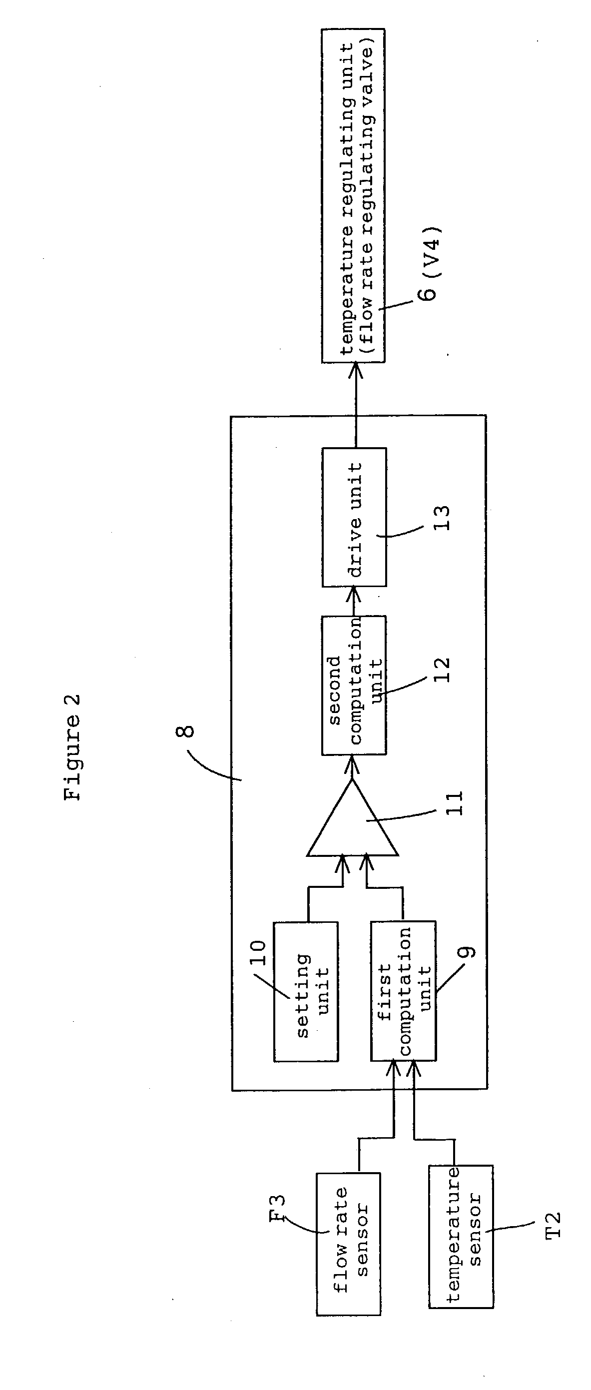
While supplying methanol and carbon monoxide via feed lines 17 and 19, respectively, to a liquid phase reaction system 3 including a carbonylation catalytic system, and maintaining a substantially constant liquid level of the reaction system, part of the reaction mixture containing the produced acetic acid is drawn out from the reaction system and supplied to a flash distillation column 4, and the high boiling point component, which contains the carbonylation catalytic system that has been separated by ths flash distillation, is circulated to the reaction system 3 by means of a circulation line 21. At circulation line 21, the flow rate is detected by a flow rate sensor F3 and the temperature is detected by a temperature sensor T2, and based on the detection data, a control unit 8 is used to control the temperature of the circulated high boiling point component by means of a temperature regulating unit 6 and thereby to suppress temperature and pressure fluctuations of the above-mentioned reaction system.

Description

[0001] This invention relates to a reaction control method (or stabilization method) and a reaction control apparatus that are useful for stabilizing a reaction system for a carbonylation reaction, etc.[0002] Carboxylic acids (such as acetic acid, etc.) and derivatives thereof (such as methyl methacrylate, etc.) are produced industrially by use of carbonylation reactions. For example, Japanese Patent Application Laid-open No. 54011 / 1973 (JP-48-54011A) discloses a carbonylation method in which an olefin, an alcohol or ester thereof, a halide, or ether derivative is allowed to react in the liquid phase with carbon monoxide in the presence of a catalytic system containing a rhodium or iridium component and an iodine or bromine component. In this process, at least part of the liquid reactants is passed without heating through a separation zone that is substantially low in pressure to vaporize at least part of an above-mentioned carbonylation product, the vaporized carbonylation product ...

Claims


Application Information

Patent Timeline
Patent Type & Authority Applications(United States)
IPC IPC(8): C07B39/00C07B61/00C07C45/50C07C51/12C07C51/44C07C53/08
CPCB01J19/0013B01J2219/00006C07C51/44C07C51/12C07B39/00B01J2219/00063B01J2219/00065B01J2219/00067B01J2219/00069B01J2219/00164B01J2219/00182B01J2219/00202B01J2219/00204B01J2219/00213B01J2219/0022B01J2219/00231B01J2219/00238C07C53/08Y02P20/582
Inventor NAKAJIMA, HIDEHIKOHARANO, YOSHIYUKI
Owner DAICEL CHEM IND LTD
Learn More