Fuel cells with integrated humidification and method for humidifying fuel cell process gas

Inactive Publication Date: 2003-10-09
VIESSMANN WERKE GMBH & CO
View PDF2 Cites 18 Cited by
  • Summary
  • Abstract
  • Description
  • Claims
  • Application Information

AI Technical Summary

Benefits of technology

0010] Thus, the invention is based on the problem to provide a fuel cell with integrated humidification which does not need external water feed systems and dosing arrangements and nevertheless enables an increas

Problems solved by technology

Although product water is used directly in this arrangement for humidifying the fuel cell, it is difficult or impossible to regulate the feedback portion of the product water.
Furthermore, an

Method used


Image

  • Fuel cells with integrated humidification and method for humidifying fuel cell process gas
  • Fuel cells with integrated humidification and method for humidifying fuel cell process gas
  • Fuel cells with integrated humidification and method for humidifying fuel cell process gas

Examples


Embodiment Construction

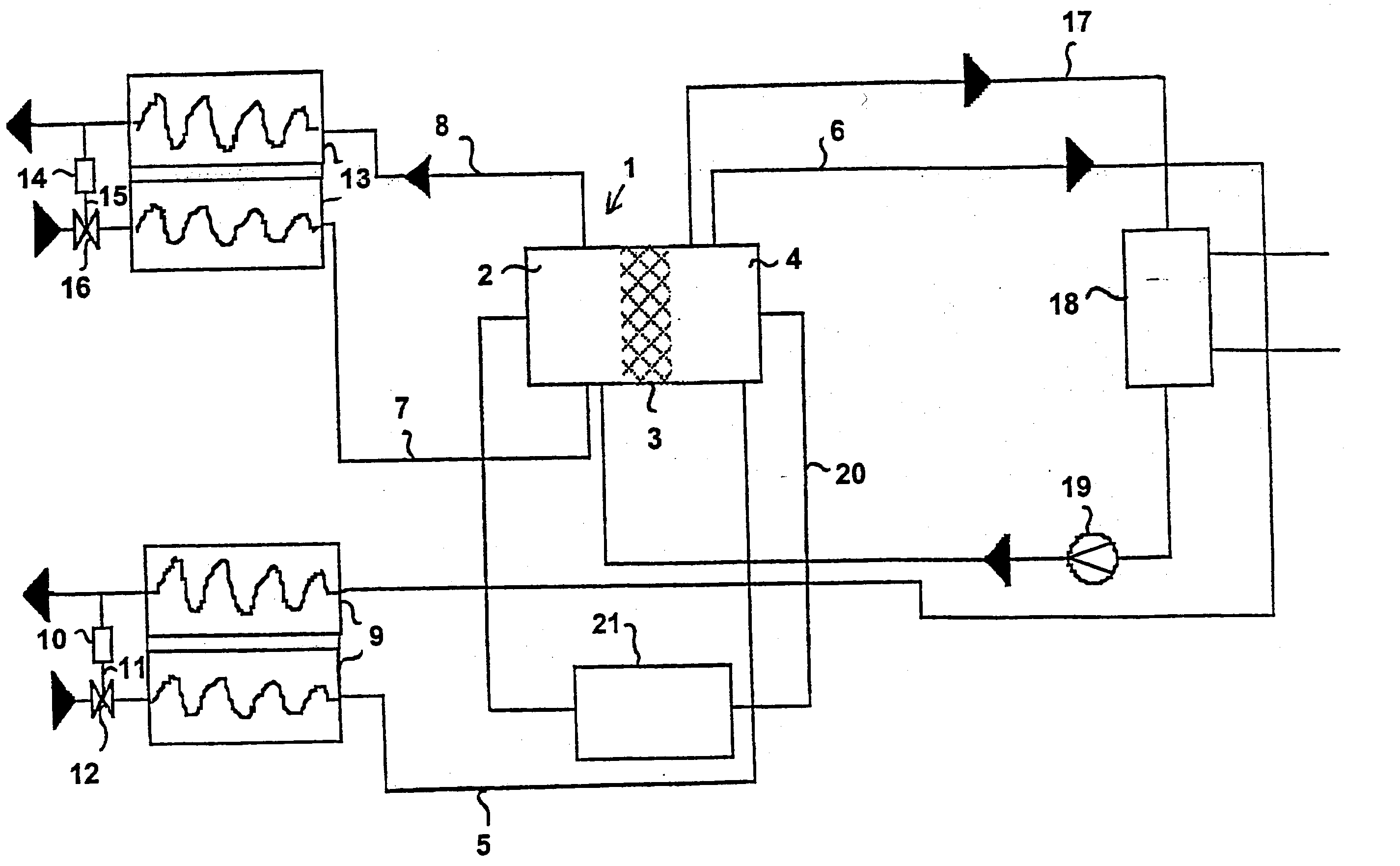
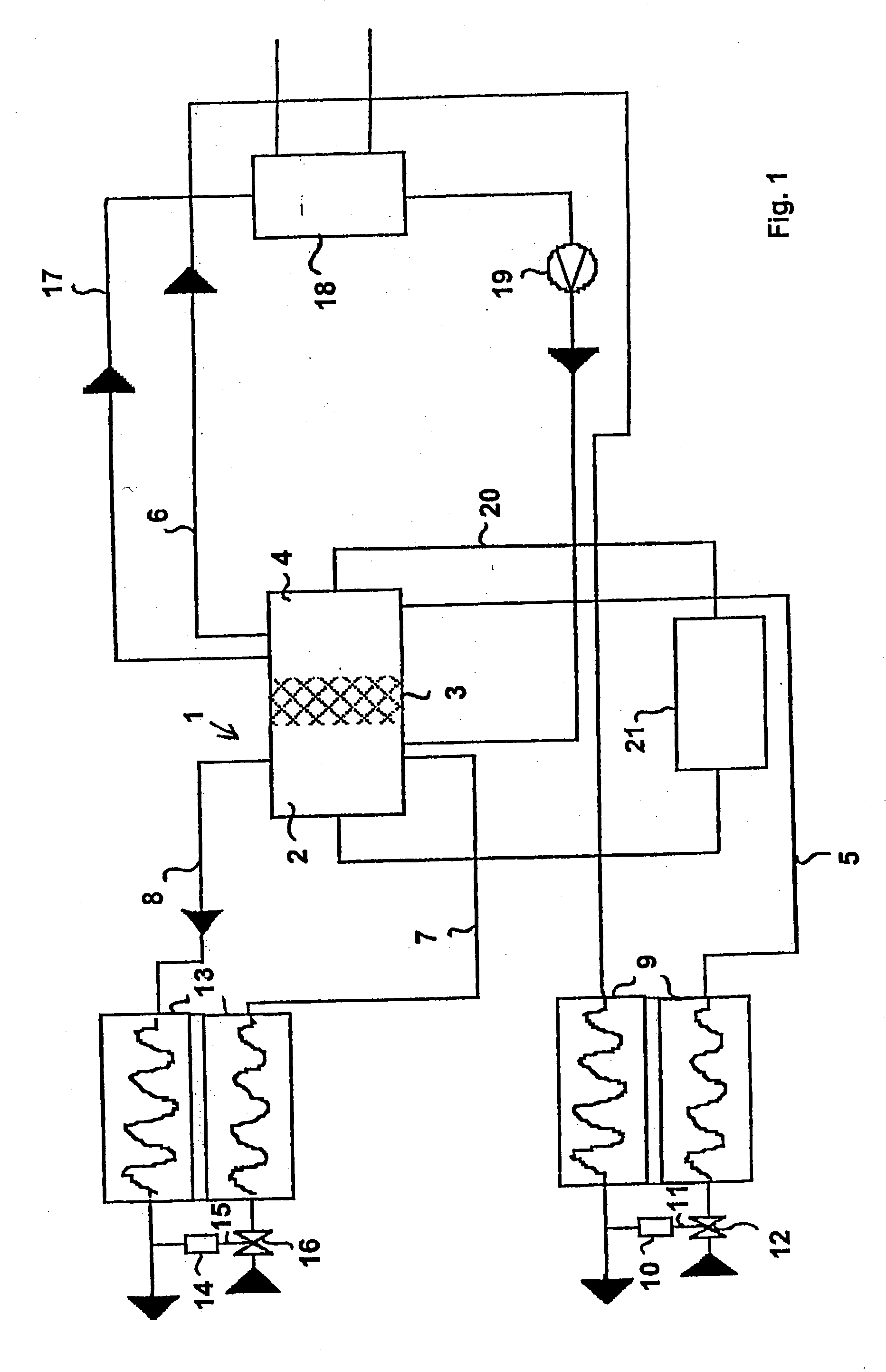
[0048] According to the arrangement shown in FIG. 1, a fuel cell with a humidification unit is set up only at the cathode side and the system with the data shown in Table 1 below is operated with respect to the humidity content of the cathode gases.

1TABLE 1 Humidity content with integrated cathode humidification Primary side = used air side BZ Flow speed .DELTA. p .DELTA. p (liters r.F. TP T r.F. TP 1,2 2,3 per T in in in out out out tube use minute) (.degree. C.) (%) (.degree. C.) (.degree. C.) (%) (.degree. C.) (mbar) (mbar) 100 59.7 100 59.7 38.4 100 38.4 19.7 29.4 150 69.7 53.5 55.9 45.5 98.2 45.2 54 63 150 61.3 100 61.3 51.7 100 51.7 54 63 Secondary side = supply air BZ Flow speed (liters r.F. r.F. TP per T in in TP in T out out out minute) (.degree. C.) (%) (.degree. C.) (.degree. C.) (%) (.degree. C.) 100 19.1 12.9 -8.9 54 67.6 46.1 150 22.6 13.1 -6.3 46.3 60.1 36.7 150 22.6 13.1 -6.3 36.1 99.1 35.9 Symbols in the table: BZ: fuel cell T in: temperature at the entry side r.F. ...


PUM


Abstract

The invention relates to a fuel cell with integrated humidification, comprising a cathode-side or anode-side humidification unit with a heat exchanger, a condensate separator, a capillary tube and a Venturi nozzle and/or pump. The invention also relates to a method for humidifying process gas for the operation of a fuel cell wherein only product water is used and wherein, according to a first embodiment, the gas containing O2 for the cathode is humidified by the cathode off-gas which contains water vapour by means of a first humidification unit and/or the combustion gas containing H2 for the anode is humidified by the anode off-gas which contains water vapour by means of a second humidification unit or wherein, according to a second embodiment, the combustion gas containing H2 for the anode is humidified by the cathode off-gas which contains water vapour by means of a first humidification unit and/or the gas containing O2 for the cathode is humidified by the anode off-gas which contains water vapour by means of a second humidification unit.

Description

[0001] 1. Field of the Invention[0002] The invention relates to fuel cells with integrated humidification as well as a method for humidifying process gas for the operation of a fuel cell.[0003] Because of their high efficiency and low pollutant and noise emission, fuel cells are very well suited for independent current generation in smaller and medium units, for traction applications, as well as for combined current- and heat generation.[0004] To avoid a desiccation of the electrolyte membrane, it is necessary with fuel cells, especially with fuel cells having proton-conducting electrolyte membranes or polymer electrolyte membranes (PEM cells) that the process gases, i.e., gas containing O.sub.2 for the cathode side and fuel gas containing H.sub.2 for the anode side, are humidified. Many methods have already been proposed for the humidification of the process gases of fuel cells.[0005] 2. Description of the State of the Art[0006] EP 0,629,014 B1 describes a method and a device for h...

Claims


Application Information

Patent Timeline
IPC IPC(8): H01M8/04H01M8/04014H01M8/04119
CPCH01M8/04014Y02E60/50H01M8/04119
Inventor SCHOLTA, JOACHIMJORRISEN, LUDWIGGAUGLER, BERND
Owner VIESSMANN WERKE GMBH & CO
Why Eureka
Try Eureka