Apparatus for performing a discectomy through a trans-sacral axial bore within the vertebrae of the spine

a trans-sacral axial bore and discectomy technology, which is applied in the direction of prosthesis, surgical forceps, therapy, etc., can solve the problems of annulus thickening, severe pain, and more rigidity

Inactive Publication Date: 2003-10-09
TRANSI
View PDF8 Cites 213 Cited by
  • Summary
  • Abstract
  • Description
  • Claims
  • Application Information

AI Technical Summary

Problems solved by technology

With aging, the nucleus becomes less fluid and more viscous and sometimes even dehydrates and contracts (sometimes referred to as "isolated disc resorption") causing severe pain in many instances.
In addition, the annulus tends to thicken, desiccate, and become more rigid, lessening its ability to elastically deform under load and making it susceptible to fracturing or fissuring.
The fissure itself may be the sole morphological change, above and beyond generalized degenerative changes in the connective tissue of the disc, and disc fissures can nevertheless be painful and debilitating.
Nevertheless, even a contained disc herniation is problematic because the outward protrusion can press on the spinal cord or on spinal nerves causing sciatica.
Another disc problem occurs when the disc bulges outward circumferentially in all directions and not just in one location.
Mechanical stiffness of the joint is reduced and the spinal motion segment may become unstable shortening the spinal cord segment.
As the disc "roll" extends beyond the normal circumference, the disc height may be compromised, and foramina with nerve roots are compressed causing pain.
Patients who suffer from such conditions can experience moderate to severe distortion of the thoracic skeletal structure, diminished ability to bear loads, loss of mobility, extreme and debilitating pain, and oftentimes suffer neurologic deficit in nerve function.
Controversy exists regarding the preferred method of performing these fusions for various conditions of the spine.
Although these procedures are less invasive than open surgery, they nevertheless suffer the possibility of injury to the nerve root and dural sac, perineural scar formation, reherniation of the site of the surgery, and instability due to excess bone removal.
This procedure has many complications including severe pain and spasm, which may last up to several weeks following injection.
Although damaged discs and vertebral bodies can be identified with sophisticated diagnostic imaging, the surgical procedures are so extensive that clinical outcomes are not consistently satisfactory.
Furthermore, patients undergoing such fusion surgery experience significant complications and uncomfortable, prolonged convalescence.
Surgical complications include disc space infection, nerve root injury, hematoma formation, and instability of adjacent vertebrae.
As a result, the spinal column can be further weakened and / or result in surgery induced pain syndromes.
Only a limited access to and alignment of S1 and L5 can be achieved by this approach because the distal ends of the straight bore and shaft approach and threaten to perforate the anterior surface of the L5 vertebral body.
The sheath or guide is advanced through the bore as the bore is made, making it not possible for the user to adjust the curvature of the bore to track physiologic features of the bone that it traverses.

Method used


Image

  • Apparatus for performing a discectomy through a trans-sacral axial bore within the vertebrae of the spine
  • Apparatus for performing a discectomy through a trans-sacral axial bore within the vertebrae of the spine
  • Apparatus for performing a discectomy through a trans-sacral axial bore within the vertebrae of the spine

Examples


Embodiment Construction

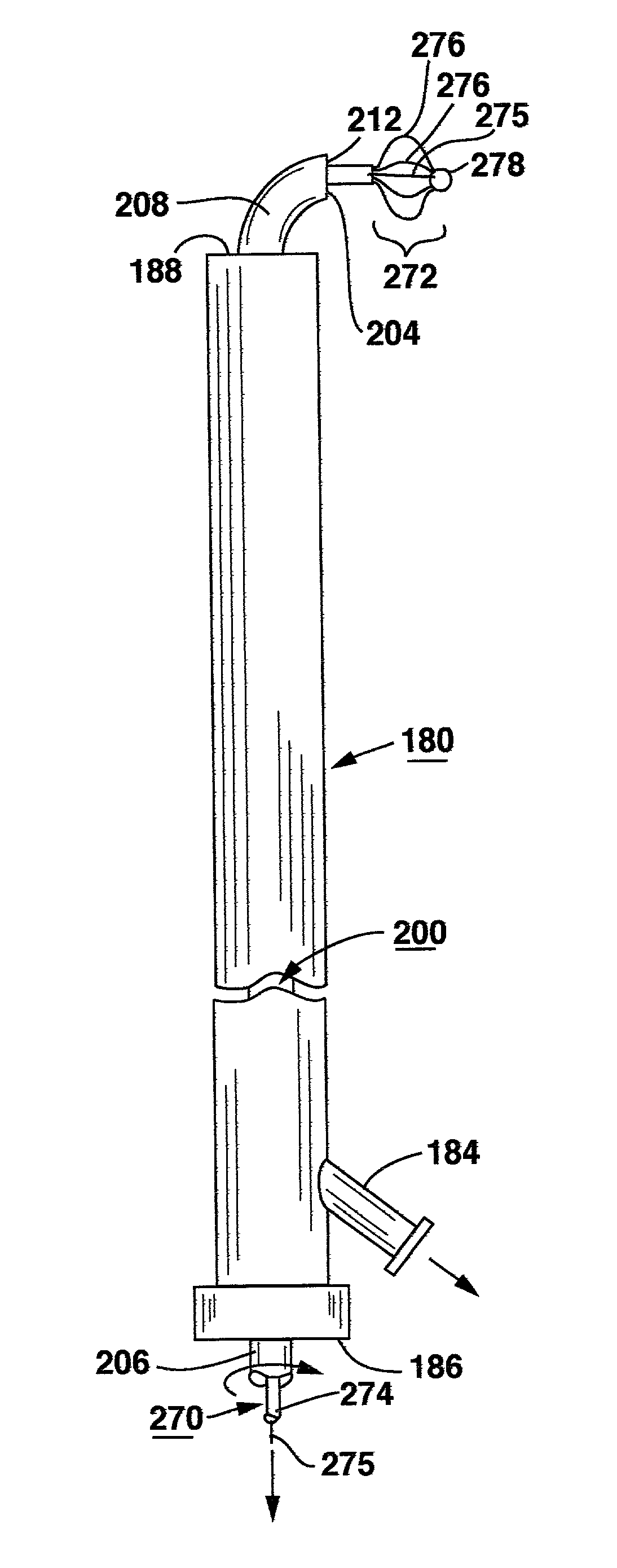
[0080] The methods and surgical instrumentation and axial spinal implants disclosed in the above-referenced provisional application No. 60 / 182,748 and in the above-referenced co-pending, commonly assigned, related patent applications can be employed in the practice of the present invention.

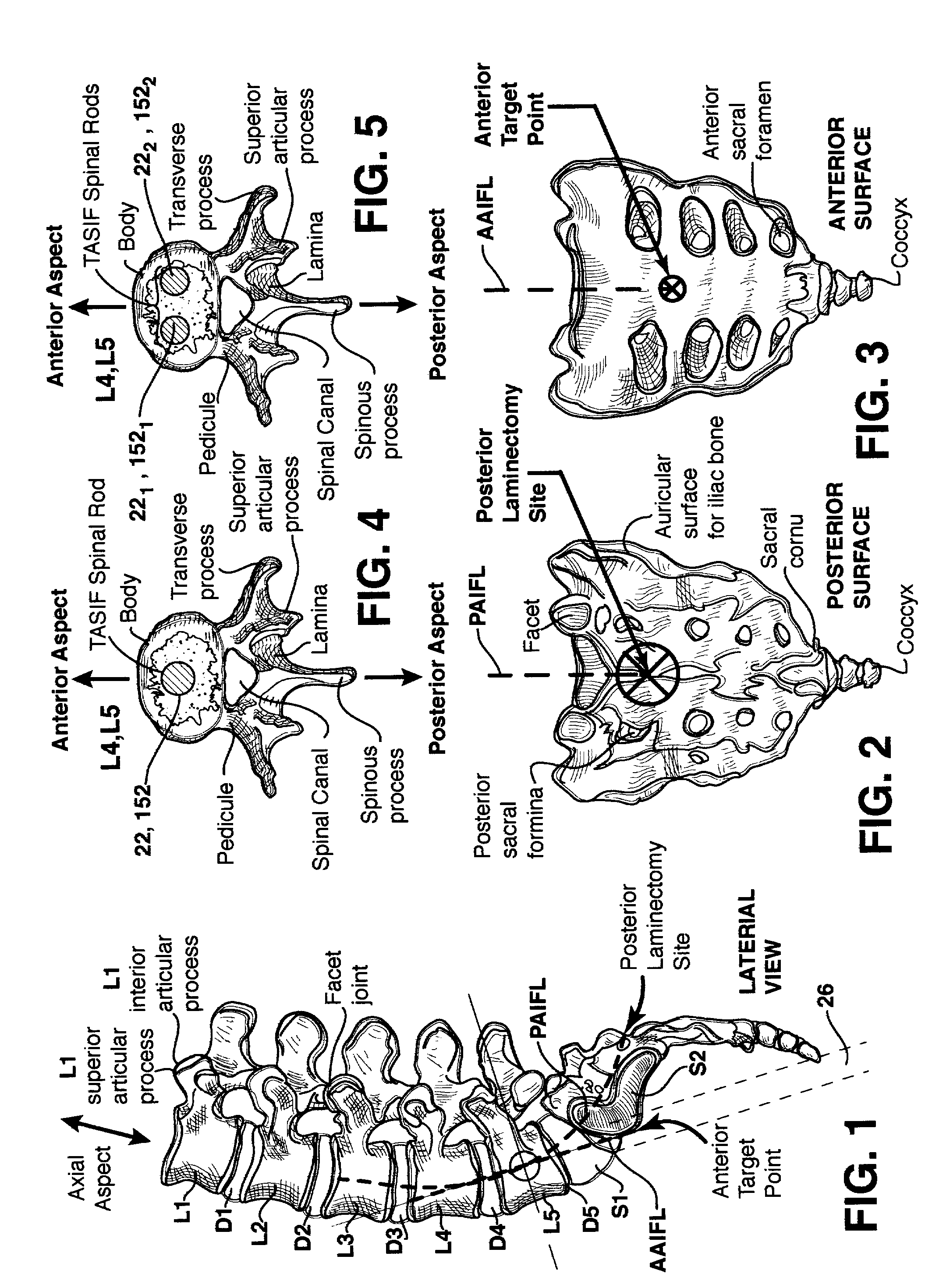
[0081] Attention is first directed to the following description of FIGS. 1-6 is taken from the above-referenced parent provisional application No. 60 / 182,748. The acronyms TASF, AAFL, and PAFL used in the '748 application are changed to TASIF, AAIFL and PAIFL in this application to explicitly acknowledge that instruments can be introduced for inspection or treatments in addition to the fusion and fixation provided by axial spinal implants that may be inserted into the axial bores or pilot holes.

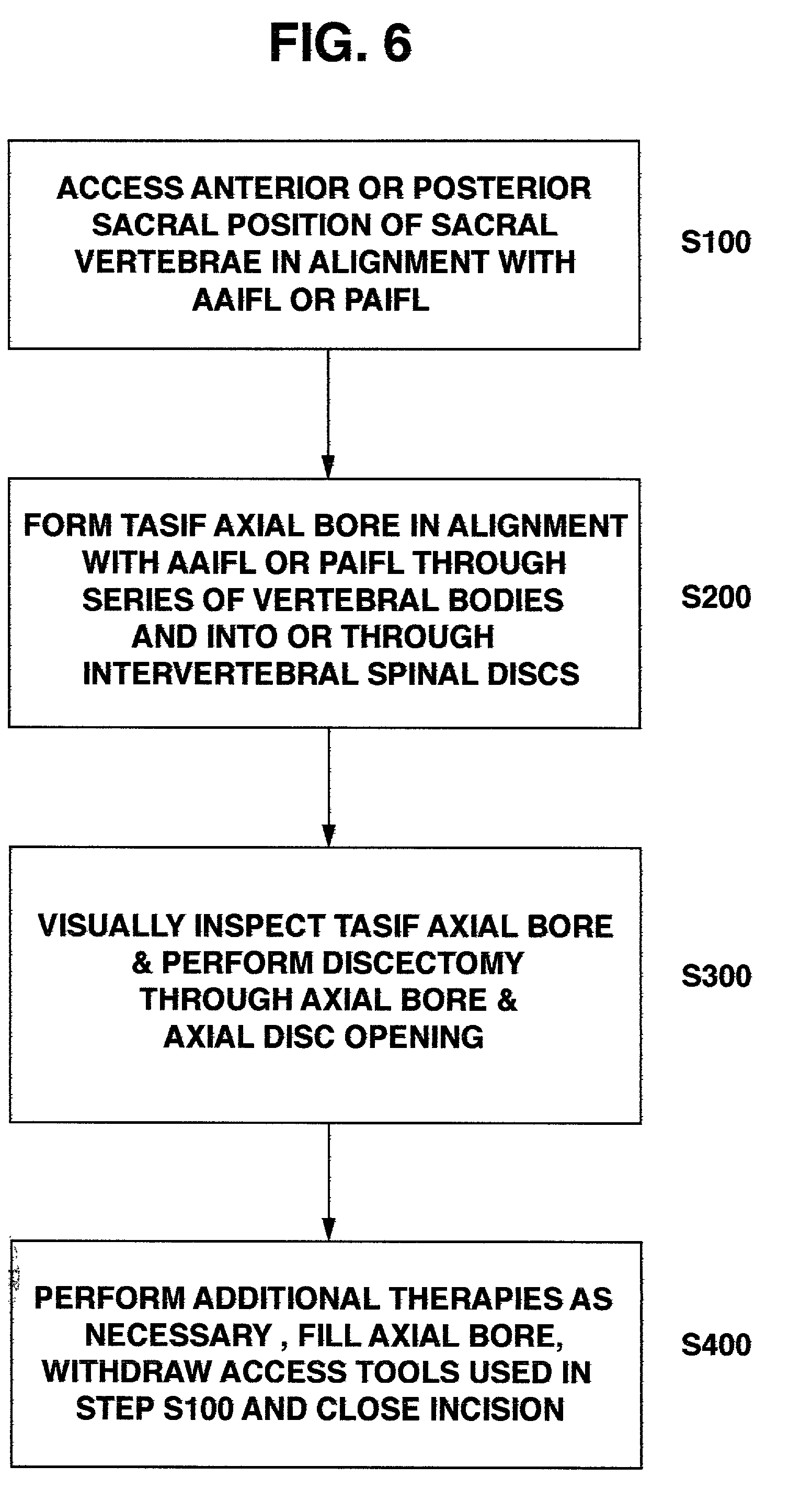
[0082] FIGS. 1-3 schematically illustrate the anterior and posterior TASIF surgical approaches in relation to the lumbar region of the spinal column, and FIGS. 4-5 illustrate the location of the TASIF impla...


PUM

PropertyMeasurementUnit
diameteraaaaaaaaaa
diameteraaaaaaaaaa
diametersaaaaaaaaaa

Abstract

Methods and apparatus for and performing a partial or complete discectomy of an intervertebral spinal disc accessed by one or more trans-sacral axial spinal instrumentation/fusion (TASIF) axial bore formed through vertebral bodies in general alignment with a visualized, trans-sacral anterior or posterior axial instrumentation/fusion line (AAIFL or PAIFL) line. A discectomy instrument is introduced through the axial bore, the axial disc opening, and into the nucleus to locate a discectomy instrument cutting head at the distal end of the discectomy instrument shaft within the nucleus. The cutting head is operated by operating means coupled to the instrument body proximal end for extending the cutting head laterally away from the disc opening within the nucleus of the intervertebral spinal disc and for operating the cutting head to form a disc cavity within the annulus extending laterally and away from the disc opening or a disc space wherein the disc cavity extends through at least a portion of the annulus. A discectomy sheath that is first introduced to extend from the skin incision through the axial bore and into the axial disc opening having a discectomy sheath lumen that the discectomy instrument is introduced through. The discectomy sheath is preferably employed for irrigation and aspiration of the disc cavity or just aspiration if irrigation fluids are introduced through a discectomy instrument shaft lumen. The cutting head of the discectomy tool is deflected from the sheath lumen laterally and radially toward the annulus using a deflecting catheter or pull wire.

Description

[0001] This application claims priority and benefits from Provisional Patent Application No. 60 / 182,748, filed Feb. 16, 2000, entitled METHOD AND APPARATUS FOR TRANS-SACRAL SPINAL FUSION.[0002] Reference is hereby made to commonly assigned co-pending U.S. patent application Ser. No. (1) 09 / 640,222 filed Aug. 16, 2000, for METHOD AND APPARATUS FOR PROVIDING POSTERIOR OR ANTERIOR TRANS-SACRAL ACCESS TO SPINAL VERTEBRAE in the name of Andrew H. Cragg, MD; (2) Ser. No. 09 / 684,620 filed Oct. 10, 2000, for AXIAL SPINAL IMPLANT AND METHOD AND APPARATUS FOR IMPLANTING AN AXIAL SPINAL IMPLANT WITHIN THE VERTEBRAE OF THE SPINE in the name of Andrew H. Cragg, MD; (3) Ser. No. 09 / 709,105 filed Nov. 10, 2000, for METHODS AND APPARATUS FOR FORMING CURVED AXIAL BORES THROUGH SPINAL VERTEBRAE in the name of Andrew H. Cragg, MD et al.; (4) Ser. No. 09 / 710,369 filed Nov. 10, 2000, for METHODS AND APPARATUS FOR FORMING SHAPED AXIAL BORES THROUGH SPINAL VERTEBRAE in the name of Andrew H. Cragg, MD et a...

Claims


Application Information

Patent Timeline
Patent Type & Authority Applications(United States)
IPC IPC(8): A61B17/00A61B17/16A61B17/56A61B17/17A61B17/22A61B17/28A61B17/32A61B17/66A61B17/70A61B17/88A61F2/00A61F2/28A61F2/30A61F2/44A61F2/46A61N5/10
CPCA61B17/1617A61N5/1027A61B17/1757A61B17/32002A61B17/3203A61B17/320725A61B17/66A61B17/70A61B17/7055A61B2017/00261A61B2017/00734A61B2017/00867A61B2017/2905A61B2017/320733A61F2/441A61F2/442A61F2/4455A61F2/4465A61F2/4601A61F2/4611A61F2002/2821A61F2002/2835A61F2002/30092A61F2002/30291A61F2002/3055A61F2002/30563A61F2002/30566A61F2002/30677A61F2002/30774A61F2002/30841A61F2002/3085A61F2002/30879A61F2002/30884A61F2002/30892A61F2002/30925A61F2002/3097A61F2002/4475A61F2002/448A61F2002/4631A61F2210/0014A61F2230/0091A61F2310/00353A61B17/1671A61F2002/30593
Inventor CRAGG, ANDREW H.KAGAN, JONATHAN
Owner TRANSI
Why Eureka
Try Eureka