
Optical coherence tomography apparatus, optical fiber lateral scanner and a method for studying biological tissues in vivo

a coherence tomography and optical fiber technology, applied in the direction of instruments, catheters, applications, etc., can solve the problems of limiting the possibility of using this device for diagnostics, unable to apply these devices for medical diagnostics, and studying samples in the direction of approximately perpendicular direction, so as to improve performance and improve data

Inactive Publication Date: 2003-11-06
IMALUX CORP
View PDF13 Cites 22 Cited by
  • Summary
  • Abstract
  • Description
  • Claims
  • Application Information

AI Technical Summary

Benefits of technology

[0015] The object of the present invention is to provide an apparatus for optical coherence tomography and an optical fiber lateral scanner, which is part of this optical coherence tomography apparatus, with improved performance data, said improved performance data making these devices suited for diagnostics of soft and hard biological tissue in vivo, in particular, for diagnostics of human cavity surfaces and human internal organs, for diagnostics of dental, bony, and cartilage biological tissue, as well as for industrial diagnostics of hard-to-access cavities of technical objects. Another object of the invention is to provide a method for studying biological tissue in vivo allowing for performing diagnostics of biological tissue covered with epithelium, in particular, of biological tissue lining the surface of human internal organs and cavities.
[0059] In vivo diagnostics of biological tissue covered with epithelium on basis of the state of basal membrane, according to the developed method, allows for early non-invasive diagnostics of biological tissue. The use of the optical fiber probe of the invention, of which the lateral scanner of the invention is a part, allows for diagnostics of the state of biological tissue lining the surface of hard-to-access cavities and internal organs of a patient, for example, by placing the optical fiber probe into an instrumental channel of an endoscope. Using low coherent optical radiation for implementing the developed method ensures high spatial in-depth resolution.

Problems solved by technology

Major disadvantage inherent in all of the above-described apparatus as well as in other known apparatus of this type is that studies of samples in the direction approximately perpendicular to the direction of propagation of optical radiation are performed either by respective moving of the samples under study or by scanning a light beam by means of bulky lateral scanners incorporated into galvanometric probes.
This does not allow these devices to be applied for medical diagnostics of human cavities and internal organs in vivo, as well as for industrial diagnostics of hard-to-access cavities.
However, although such geometry allows for introducing the probe into various internal cavities of human body and industrial objects, the presence of an external relative to the optical fiber probe lateral scanner and scanning the difference in the optical lengths of the sampling and reference arms by means of mechanical movement of the reference mirror significantly limit the possibility of using this device for performing diagnostics of surfaces of human cavities and internal organs in vivo, as well as for industrial diagnostics of hard-to-access cavities.
This device allows imaging of walls of thin vessels, but is unsuitable as a diagnostic means to image surfaces of cavities and internal organs inside a human body, as well as for industrial diagnostics of hard-to-access large-space cavities.
A disadvantage of this apparatus is that it is not fit for diagnostics of surfaces of hard-to-access internal human organs in vivo, such as, for example, stomach and larynx, and for industrial diagnostics of surfaces of hard-to-reach cavities of technical objects.
A disadvantage of devices of this type is that the amplitude of optical fiber deflection is limited by the allowable mass of the magnet fixedly attached to the optical fiber (from the point of view of sagging), and by difficulties in inducing alternate magnetic field of sufficient strength when the device is to have small dimensions.
In this device the small mass of the magnet limits the strength of the induced field, which, in turn, limits the amplitude of optical fiber deflection, An increase in the amplitude of deflection due to an increase in the field strength is impossible since this would require currents much exceeding damaging currents for thin-film conductors.
Besides, the array of thin-film conductors, being positioned across the direction of propagation of an optical radiation beam, disturbs the continuity of scanning, thus resulting in loss of information.
In this device the field strength induced by the current conductor, when control current is applied, is limited by a small mass of the conductive coating, thus limiting the deflection amplitude of the optical fiber.
Thus, a disadvantage of this lateral scanner, as well as of other known lateral scanners, is that it is impossible to provide necessary performance data, in particular, miniature size, simultaneously with required deflection amplitude of the optical fiber to incorporate such a device in an optical fiber probe of an optical fiber interferometer, which is part of a device for optical coherence tomography suited for diagnostics of surfaces of hard-to-access human internal organs in vivo, as well as for industrial diagnostics of hard-to-reach cavities.
However, this method, as well as other known methods, is not intended for performing diagnostics of biological tissue covered with epithelium.

Method used


Image

  • Optical coherence tomography apparatus, optical fiber lateral scanner and a method for studying biological tissues in vivo
  • Optical coherence tomography apparatus, optical fiber lateral scanner and a method for studying biological tissues in vivo
  • Optical coherence tomography apparatus, optical fiber lateral scanner and a method for studying biological tissues in vivo

Examples


Embodiment Construction

[0068] The operation of the developed apparatus for optical coherence tomography and the developed optical fiber probe will be best understood from the following description of carrying out the method for diagnostics of biological tissue in vivo.

[0069] The method for diagnostics of biological tissue in vivo is carried out the following way.

[0070] An optical beam in the visible or IR range is directed, for instance, with the aid of a laser, toward a biological tissue under study, the later being a biological tissue covered with epithelium. An image of the biological tissue covered with epithelium is obtained by visualizing the intensity of back-scattered optical radiation beam with, for example, a confocal microscope. In the acquired image, the basal membrane is identified, which separates the epithelium from underlying stroma. Diagnostics is made on basis of the state of said basal membrane.

[0071] In a specific embodiment, said biological tissue covered with epithelium is a biologic...


PUM

PropertyMeasurementUnit
diameteraaaaaaaaaa
diameteraaaaaaaaaa
optical lengthaaaaaaaaaa

Abstract

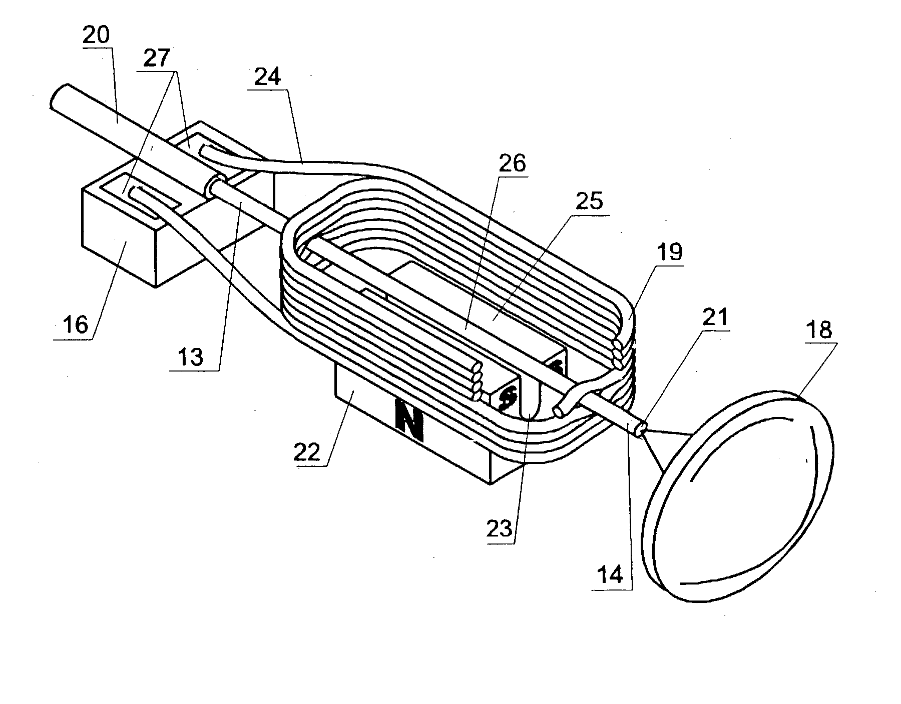
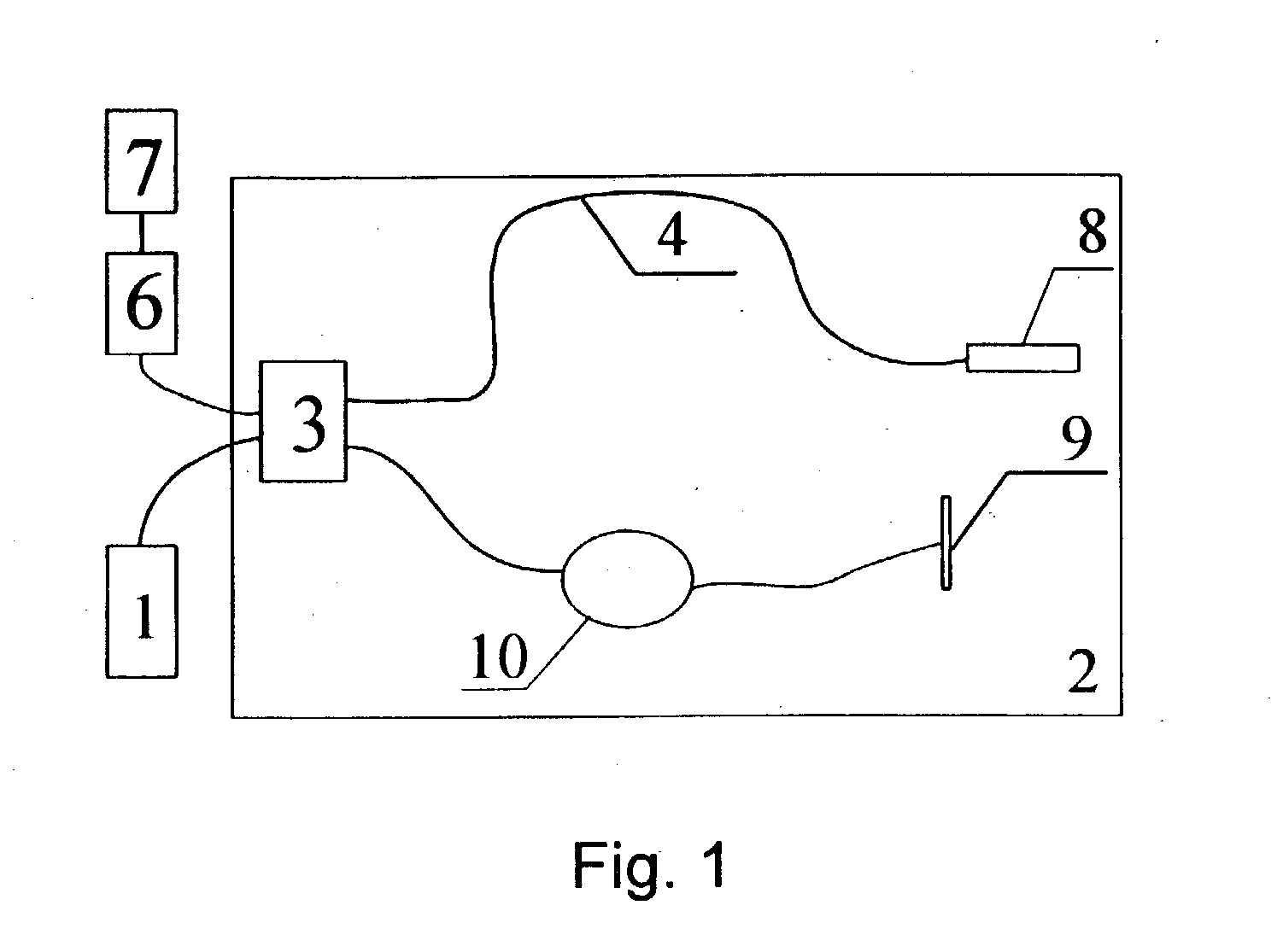
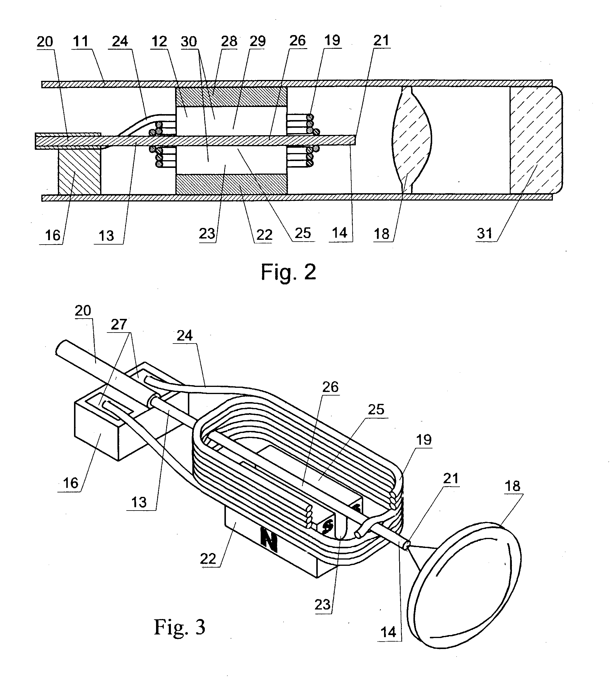
The present invention relates to the analysis of the internal structures of objects using optical means. According to the invention there were designed an apparatus suited for optical coherence tomography (OCT), an optical fiber lateral scanner (15), which is a part of said apparatus and is incorporated into an optical fiber probe (8), and a method for studying biological tissue in vivo, which allows for making a diagnostics of the biological tissue under study on basis of the state of the basal membrane (46). The moving part of lateral scanner (15) of sampling arm (4) of interferometer (2) is arranged comprising a current conductor (19), which envelopes a magnetic system (17) in the area of one of its poles (25) and an optical fiber (13), which is rigidly fastened to current conductor (19), whereas optical fiber (13) serves as a flexible cantilever, allowing to miniaturize the optical fiber probe (8). Constructing magnetic system (17) as two permanent magnets (22, 28) which are aligned at their analogous poles (25, 29), and placing optical fiber (13) in a throughhole (30), the throughhole (30) being formed by the facing grooves made in said analogous poles (25, 29) of permanent magnets (22, 28), ensure optimization of the design of optical fiber probe (8), the body (11) of said optical fiber probe (8) having limited dimensions. Optical fiber probe (8) is placed at the distal end of an instrumental channel of an endoscope or borescope. Studying of biological tissue in vivo with the aid of the developed apparatus allows for non-invasive diagnostics of biological tissue on basis of the state of basal membrane (46).

Description

[0001] The present invention relates to physical engineering, in particular, to the study of internal structure of objects by optical means, and can be applied for medical diagnostics of individual organs and systems of human body in vivo, as well as for industrial diagnostics, for example, control of technological processes.[0002] In recent years, there has been much research interest in the optical coherence tomography of scattering media, in particular, biological tissues. Optical coherence tomography apparatus are fairly well known and comprise a low coherent light source and an optical interferometer, commonly designed as either a Michelson optical fiber interferometer or a Mach-Zender optical fiber interferometer.[0003] For instance, an optical coherence tomography apparatus known from the paper by X.Clivaz et al., "High resolution reflectometry in biological tissues", OPTICS LETTERS, Vol. 17, No. 1, Jan. 1, 1992, includes a low coherent light source and a Michelson optical fi...

Claims


Application Information

Patent Timeline
Patent Type & Authority Applications(United States)
IPC IPC(8): G01N21/17A61B1/005A61B5/00A61B6/08A61B10/00G01B9/02G01B9/04G02B26/10
CPCA61B1/00096A61B1/00172A61B1/00177A61B1/00183A61B1/005A61B5/0066G01B2290/65G01B9/04G02B26/10G01B9/02002G01B9/0205G01B9/02091A61B5/6852
Inventor GELIKONOV, VALENTIN M.GELIKONOV, GRIGORY V.GLADKOVA, NATALIA D.SHAHOVA, NATALIA M.FELDCHTEIN, FELIX I.SERGEEV, ALEXANDER M.
Owner IMALUX CORP
Learn More