Rapid multi-material sample input system

a multi-material and input system technology, applied in the field of material transfer technology, can solve the problems of pulsatile flow characteristics, fluid stream velocity variation, and unresolved significant problems with these conventional material transfer technologies, and achieve the effects of increasing the core width, and reducing the number of significant problems

Inactive Publication Date: 2003-11-13
CYTOMATION +1
View PDF99 Cites 61 Cited by
  • Summary
  • Abstract
  • Description
  • Claims
  • Application Information

AI Technical Summary

Benefits of technology

[0016] It is therefore, a broad object of embodiments of the invention to introduce discrete amounts of material into a continuous fluid stream. One aspect of this object can be to introduce discrete amounts of material without substantially changing the volume or the pressure of the fluid stream. Another aspect of this object can be to introduce discrete amounts of material into a fluid stream without substantially disrupting the laminar flow of the fluid stream. A third aspect of this object can be to introduce discrete amounts of material into a liquid fluid stream without introducing substantial amounts of gas.
[0017] Another significant object of embodiments of the invention can be to rapidly serially introduce a number of materials into a fluid stream in a short duration of time. One aspect of this object of the invention can be to introduce discrete amounts of different materials into a fluid stream serially about every 500 microseconds to about every 1 second. A second aspect of this object of the invention can be to accomplish such rapid introduction of different materials into the fluid stream without substantially disrupting the continuous fluid stream. A third aspect of this object of the invention can be to accomplish rapid introduction of different materials into a continuous fluid stream without a significantly broadening the fluid stream width as it exits a flow path into a larger laminar fluid stream flow.
[0019] Another significant object of embodiments of the invention can be to introduce biological materials, such as cells, into a fluid stream in sufficient numbers to establish a concentration that maintains the extracellular environment within a range compatible with biological functioning of the cells. One aspect of this object can be to maintain rapid introduction of different discrete amounts of materials or cells into the fluid stream at a pressure that does not substantially increase the core width of the stream as it exits the flow path into a larger laminar flow fluid stream. For example, flow cytometry embodiments of the invention can maintain the core width of the fluid stream containing separate discrete amounts of cells at a width between about two (2) micrometers to about three (3) micrometers at a pressure of about 66 pounds per square inch when ejected into a laminar flow sheath fluid stream having a pressure of 60 pounds per square inch. Importantly, the difference between the pressure of the fluid stream and the laminar flow into which the fluid stream is ejected is only about 6 pounds per square inch. As such, there is little retardation of the stream velocity and the core width can remain substantially the same as the flow path from which it was ejected.
[0020] Another significant object of embodiments of the invention can be to minimize cross contamination between separate discrete amounts of material even at high introduction rates into a fluid stream.
[0021] Another significant object of the invention can be to provide a selectably engaged flow path that can be rotationally engaged using single direction of rotation. One aspect of this object can be to eliminate conventional reciprocating flow path switching technology. A second aspect of this object of the invention can be to reduce the number of components comprising the selectably engaged flow path. A third aspect of this object can be to increase the speed at which the selectably engaged flow path can operate or the speed at which the serial steps of engaging a plurality of flow paths can be accomplished.

Problems solved by technology

Understandably, there is great interest in increasing the rate at which small discrete amounts of material can be introduced into fluid streams because it can be the rate limiting step in analyzing the characteristics of the materials studied.
However, a number of significant problems remain unresolved with respect to these conventional material transfer technologies.
A significant problem with conventional material transfer technology may be the creation of pulsatile flow characteristics (variations in pressure or volume or both) in the fluid stream.
Even with advanced fluid stream compensation technology these volume and pressure differences can make cell differentiation or cell sorting less efficient, impractical, or even impossible.
Another significant problem with conventional material transfer technology may be that bubbles are introduced into a liquid fluid stream.
Delivering gas bubbles with the material to be analyzed, whether inadvertent or not, may not be compatible with some types of material differentiation technology, such as flow cytometry and high pressure liquid chromatography.
Another significant problem with conventional material transfer technology may be that it requires too much time to introduce material into the fluid stream and deliver the material to the material differentiation system.
Another significant problem with conventional material transfer technology may be that the core stream entraining material within a laminar flow path can be too wide.
Another significant problem with conventional material transfer technology may be that material introduced into the flow path has a concentration outside the range suitable for biological applications.
With respect to the coincident events above-described as an example, attempts to reduce the concentration of cells per unit volume in a liquid stream by dilution can alter the extracellular environment so that it is no longer consistent with the normal functioning of the cells.
Another significant problem with conventional material transfer technology may be that rapidly introducing discrete amounts of materials into a fluid stream cross contaminates (mixes a portion of one discrete amount of material with a second discrete amount of material) the materials.
This can be particularly problematic when the materials in the respective flow paths cling to the surfaces of the flow paths.
As such, conventional flow path switching technology can require relatively lengthy periods to evacuate the flow path of a first material prior to introducing a second material.

Method used


Image

  • Rapid multi-material sample input system
  • Rapid multi-material sample input system
  • Rapid multi-material sample input system

Examples


Embodiment Construction

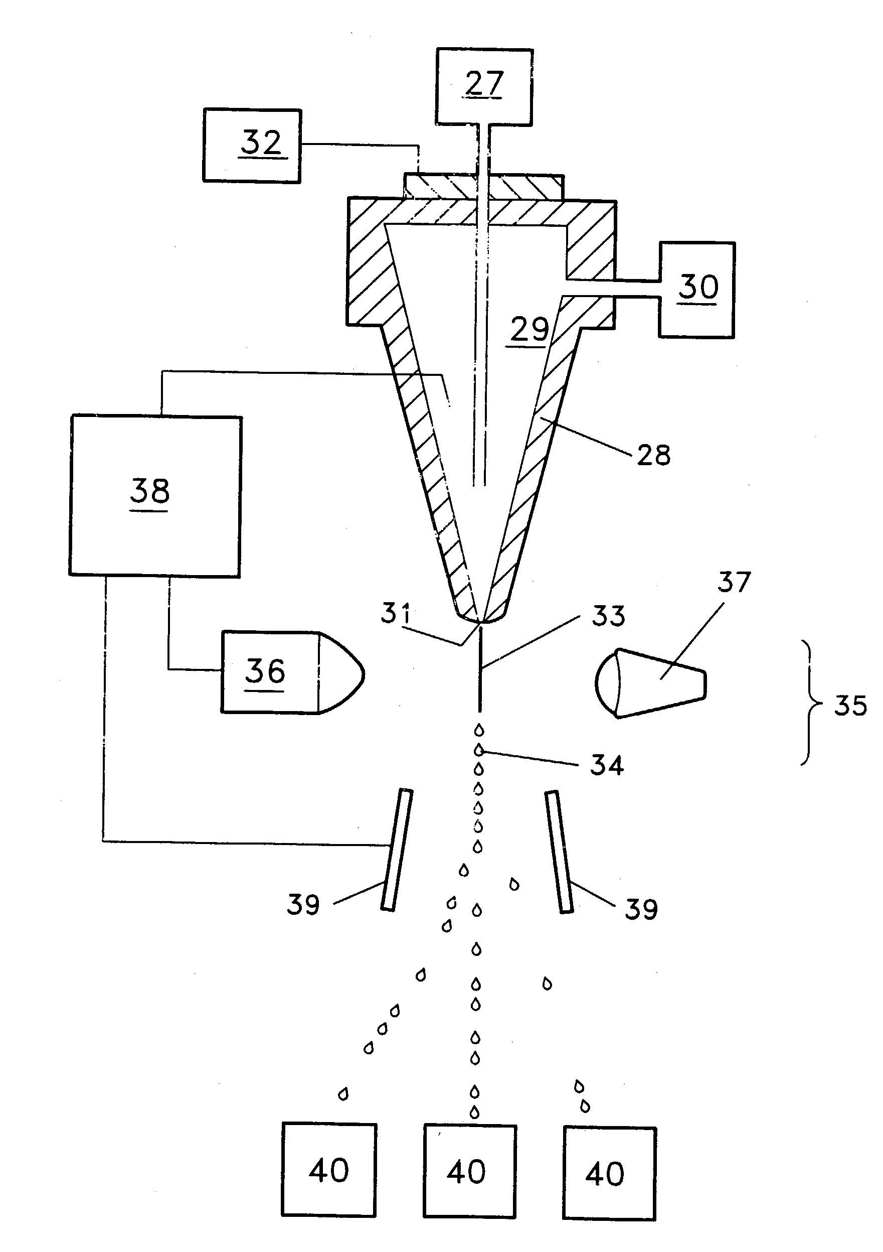
[0041] The invention involves material transfer technology that apportions discrete amounts of material and introduces the apportioned material into a flow path to provide a plurality of separate materials within a continuous fluid stream that can be delivered to numerous material differentiation technologies for analysis.

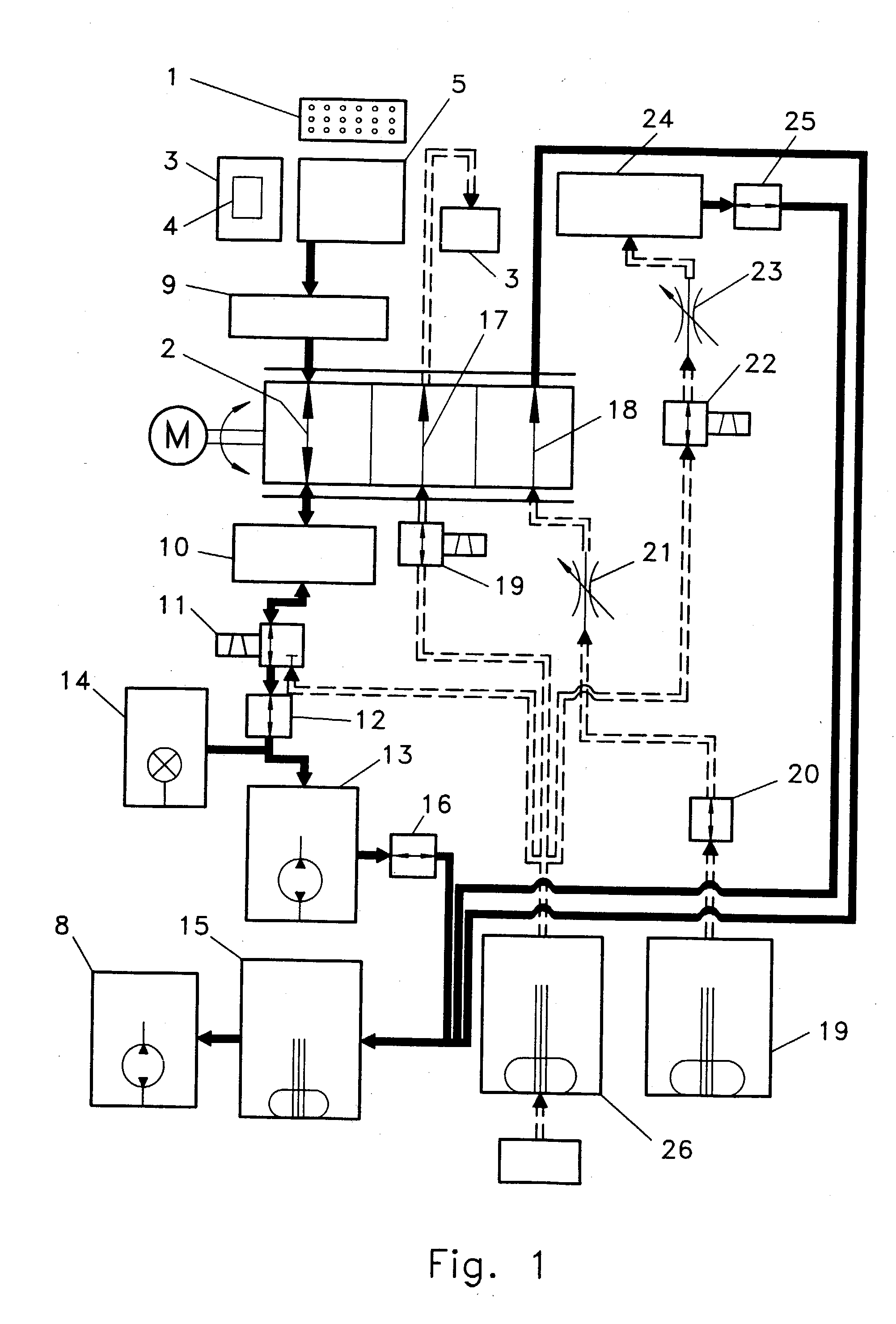
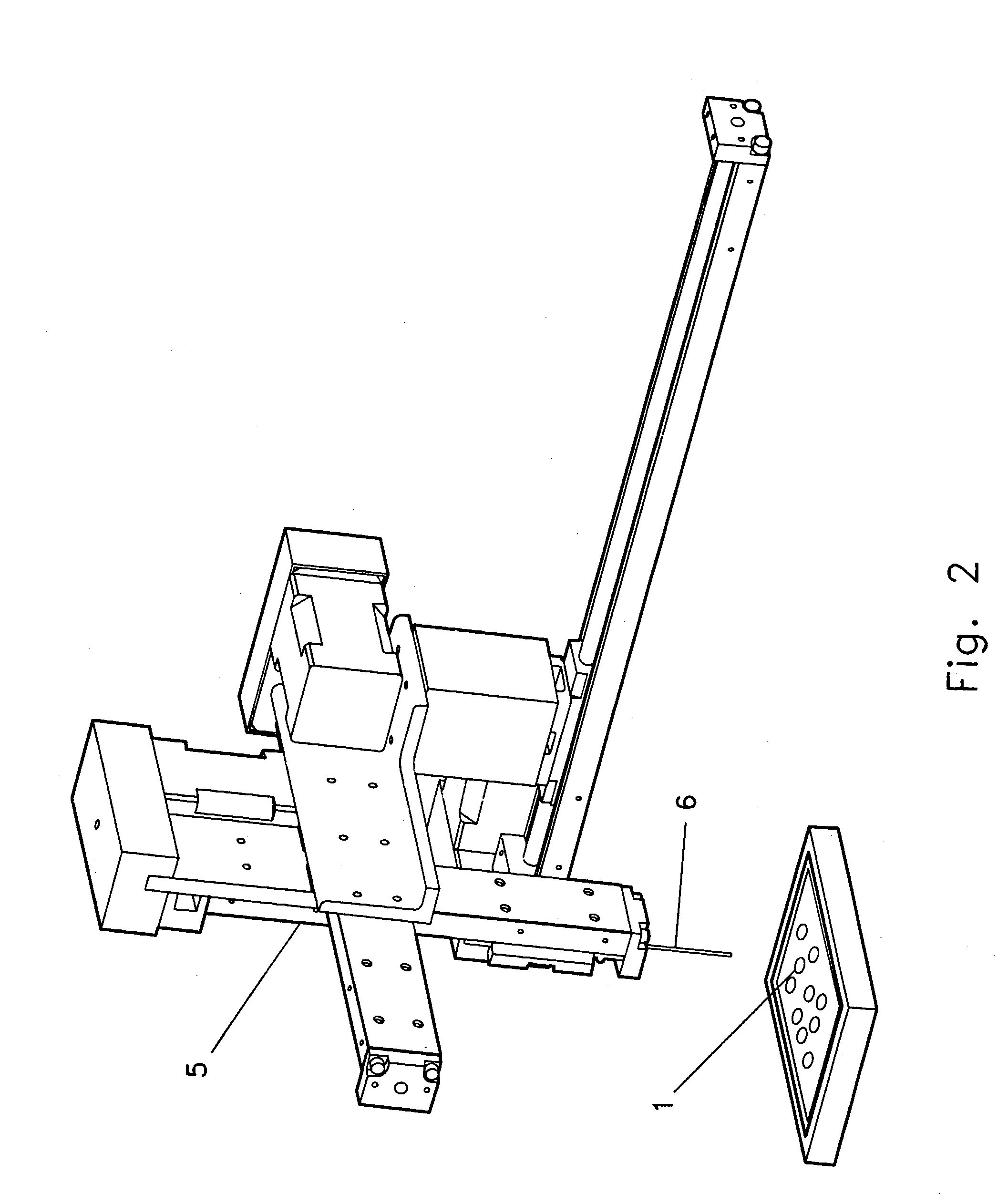
[0042] Now referring to FIG. 1, a preferred embodiment of a material transfer invention is shown. A basic embodiment of such a material transfer invention can comprise at least one material (1) having material location coordinates and a selectably engaged flow path (2) at least a portion of which can be fluidicly coupled to a material differentiation system (3). The material (1) transferred by the various embodiments of the invention can be any material that can flow within the selectably engaged flow path (2).

[0043] With respect to some embodiments of the invention, the material (1) can be a liquid, such as, water, solvents, reagents, cell culture media, stains, f...


PUM

PropertyMeasurementUnit
volumeaaaaaaaaaa
volumeaaaaaaaaaa
volumeaaaaaaaaaa

Abstract

Material transfer technology that apportions discrete amounts of material (1) and introduces the apportioned material into a selectably engaged flow path (17) to provide a plurality of separate materials within a continuous fluid stream that can be delivered to numerous material differentiation technologies (3) for analysis.

Description

[0001] This application claims the benefit of U.S. Provisional Application No. 60 / 205,730, filed May 19, 2000, and that application is hereby incorporated by reference.I. TECHNICAL FIELD[0002] Material transfer technology that apportions discrete amounts of material and introduces the apportioned material into a flow path to provide a plurality of separate materials within a continuous fluid stream that can be delivered to numerous material differentiation technologies for analysis or separation.II. BACKGROUND[0003] The rapid supply of discrete amounts of material to a continuous fluid stream for analysis by various types of material differentiation technologies, such as, chromatographs, mass spectrometers, flow cytometers, fluorometers, spectrophotometers, or the like has numerous applications such as the profiling of pharmacological compounds, the study of ligand-receptor kinetics, estimating the number of individual particles within populations, and so forth. Understandably, ther...

Claims


Application Information

Patent Timeline
Patent Type & Authority Applications(United States)
IPC IPC(8): G01N1/00G01N15/14
CPCG01N15/1456G01N2015/149G01N35/1097
Inventor BUCHANAN, KRIS S.
Owner CYTOMATION
Why Eureka
Try Eureka